 |
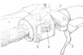
4. Controls and devicesOn a control surface from a left-hand side (fig. 4) are established: a clutch lever 1, switch of the signalling system and lever of a decompressor 3. Clutch lever. At clicking the lever the clutch is switched off also engine is detached from a gear box. Screws adjusting to dispose a groove to a tube of a control surface. The switch of the signalling system. The switch of the signalling system has switches: light of a head lamp 2 with two locked positions - Short-range light and Distant light; the indexes of turn 4 with three locked positions: mean - the turn on the left, dextral - turn to the right is switched off, left-hand -; the disconnecting switch of a sound signal 5. The lever of a decompressor. By clicking the lever make valve crack of a decompressor for purging the barrel. On a control surface from the dextral party (fig. 5) are established: the handle of the throttle of the carburettor 4, lever of a fuel corrector 7, lever of the brake of a forward sprocket 3, barrel of a main hydraulic drive of the brake 1, switch combined. The lever of a fuel corrector. At turn of the lever clockwise mix is enriched (corrector open). The lever of the brake of a forward sprocket. The clicking the lever actuates the brake of a forward sprocket, thus the lamp of XOFF in back lanterns of a motorcycle ignites.
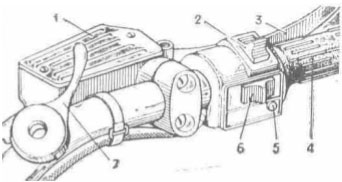
Fig. 4. Controls on a control surface at the left: 1 - clutch lever; 2 - switch of light of a head lamp; 3 - lever of a decompressor; 4 - switch of turn indicators; 5 - disconnecting switch of a sound signal Throttle lever of the carburettor. The throttle lever of the carburettor (handle of gas) is arranged on a control surface on the right. At turn of the handle by itself revolutions of a crankshaft of the engine are augmented, from itself - are reduced. The switch combined. The switch combined has: the switch of a mode of lighting with three fixed rule: dextral - is switched off, mean - the clearance lights are included, left-hand - are included main light of a head lamp and clearance lights; an emergency shut-down of the engine with two locked positions: lower - operational mode, upper - the ignition is switched off, the switch of the signalling system by distant light of a head lamp 5 - actuates light of a head lamp at clicking the push button irrespective of a rule of the switch of a mode of lighting.
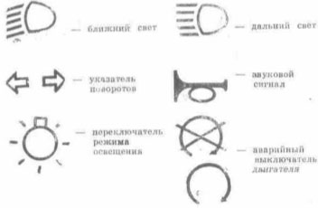
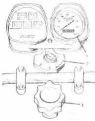
Fig. 5. Controls on a control surface on the right: 1 - barrel of the main brake; 2 - emergency shut-down of the engine; 3 - lever of the brake of a forward sprocket; 4 - handle of the throttle of the carburettor; 5 - switch of the signalling system by distant light of a head lamp; 6 - switch of a mode of lighting; 7 - lever of a fuel corrector The notations of characters indicated on switches, are adduced in a fig. 6. Shield of devices. Shield of devices 1 (fig. 7). In a nem the indicating lights are located a speedometer. The speedometer has a speed indicator and two countable units: the meter of general run and meter of a daily run. For the installation of the meter of a daily run in initial (on "0") rule to turn the handle on shield of devices to the left, as is indicated by a finger. On your motorcycle the red lamp IGNITION is not connected. She is intended for the control of ignition switch - on and activity of a generating set on motorcycles with a battery contact system of ignition and generator with electromagnetic excitation.
Fig. 6. Characters of controls
Fig. 7. Shield of devices: 1 - shield of devices; 2 - ignition switch; 3 - handle of the control damper ATTENTION! The switch of the signalling system and switch combined are captured on a control surface by plastic pins, the rule is not subject to their regulation. Green lamp a neutral POSITION. Green lamp a neutral POSITION - lamp of the control of actuation of a neutral rule between I and II by transmissions in a gear box. Green lamp TURN. Green lamp TURN with fingers - lamp of the control of a system of turn indicators. At actuation of lanterns of turn indicators by the switch the lamp should flash in phase opposition with lamps of lanterns. At burnout of one of lamps in lanterns of the indexes of turn the frequency of flashing is augmented approximately twice. The lamp at actuation burns permanently is testify to short circuit in lanterns or fault of the interrupter of turn indicators. Cyan lamp D. LIGHT. Cyan lamp D. LIGHT - the lamp indicates about actuation of distant light. Red lamp OIL. Red lamp OIL - lamp of the control of activity of a separate lubricating system of the engine. Should shine at live ignition and inoperative engine (if there is submission of oil shine does not owe). Be close to signals of lamps, it will help correctly to exploit a motorcycle. The handle of the control damper. The handle of the control damper 3 (fig. 7) arranged above a control surface in mid-range. The damper of a friction type serves for damping oscillations of a forward sprocket and control surface. Ignition switch. Ignition switch 2 (the fig. 7) has following rules of a key: OFF - all customers of a current are switched off; 1 - the circuits of ignition, lighting, signalling system, XOFF, lamp of a neutral position and control of activity of a separate lubricating system of the engine are included; 2 - the clearance lights (parking) are included. On the panel of the disconnecting switch (fig. 8) there are plugs For hooking up of customers of the electric power according to the electrical circuit (see appendix 7).
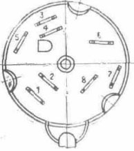
Fig. 8. Ignition switches It is recommended at exploitation of a motorcycle to keep track of by a condition of apposition of wires to terminals, not enabling their oxidation. In the autumn-winter season in a recessed square to fill up 3... 5 drips of a braking liquid.
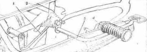
Fig. 9. The installation of the lever of the brake of a back sprocket: 1 - thrust of the brake; 2 - thrust of the switch of XOFF; 3 - lever of the brake of a back sprocket; 4 - cylinder of a step of the driver The lever of the brake of a back sprocket. The lever of the brake of a back sprocket (fig. 9) is arranged on the dextral party of a motorcycle. By clicking the lever actuate the brake of a back sprocket, thus the lamp of XOFF in a rear canopy of a motorcycle light up. The lever of a releaser. The lever of a releaser 17 (fig. 11) is arranged on a left-hand side of the engine, the launch of the engine makes by clicking the lever by a leg. Change-over lever of transmissions. The change-over lever of transmissions 18 (fig. 11) arranged on a left-hand side of the engine. The neutral position is between I and II by transmissions. The actuation I of transmission from a neutral rule is made by clicking a pedal of the lever downwards.
|