|
Chapter 1. Routine maintenance and Servicing
Degrees of difficulty
| Easy, suitable for novice with little experience |
 |
| Fairly easy, suitable for beginner with some experience |
 |
| Fairly difficult, suitable for competent DIY mechanic |
 |
| Difficult, suitable for experienced DIY mechanic |
 |
| Very difficult, suitable for expert DIY or professional |
 |
Specifications
Engine
| Oil capacity at oil change: |
|
| 600 models |
3.0 lit (3.2 US qt, 5.3 Imp pt) |
| 1000 models |
Not available |
| Oil capacity at oil and filter change: |
|
| 600 models |
3.4 lit (3.6 US qt, 6.0 Imp pt) |
| 1000 models |
3.8 lit (4.0 US qt, 6.7 Imp pt) |
| Oil capacity after disassembly: |
|
| 600 models |
4.0 lit (4.2 US qt, 7.0 Imp pt) |
| 1000 models |
4.5 lit (4.8 US qt, 8.0 Imp pt) |
| Coolant capacity: |
|
| 600 models |
2.0 lit (2.1 US qt, 3.5 Imp pt) |
| 1000 models |
3.0 lit (3.2 US qt, 5.3 Imp pt) |
| Spark plug type: |
|
| All 600 models and 1000 T model onward |
NGK DPR8EA-9 or ND X24EPR-U9 |
| 1000 H, J, K, L, M, N, P, R, S models |
NGK DPR9EA-9 or ND X27EPR-U9 |
| Spark plug gap |
0.8 - 0.9 mm (0.032 - 0.035 in) |
| Inlet valve clearance (cold): |
|
| 600 models |
0.14 - 0.18 mm (0.006 - 0.007 in) |
| 1000 models |
0.10 ±0.02 mm (0.004 ±0.001 in) |
| Exhaust valve clearance (cold): |
|
| 600 models |
0.18 - 0.22 mm (0.007 - 0.009 in) |
| 1000 H, J, K, L, M, N models |
0.16 ± 0.02 mm (0.006 ± 0.001 in) |
| 1000 P models onward |
0.18 ±0.02 mm (0.007 ±0.001 in) |
| Idle speed: |
|
| 600 California models |
1300±100rpm |
| All other 600 models |
1200±100rpm |
| 1000 L California models |
1050±100rpm |
| 1000 P onward California models |
1100±100rpm |
| All other 1000 models |
1000±100rpm |
Miscellaneous
|
Freeplay
adjustments: |
|
|
|
Throttle
cable freeplay - at twist grip flange |
2 - 6 mm
(0.08 - 0.24 in) |
|
|
Clutch
cable freeplay (600 models) - at lever ball end |
10 -20
mm (0.4 -0.8 in) |
|
|
Final
drive chain |
15-25 mm
(0.6-1.0 in) |
|
|
Front
forks: |
|
|
|
Standard
air pressure - all 600 models and 1000 H, J models |
0 - 6
psi (0 - 0.4 Bar) |
|
|
Tyre
pressures � cold |
Front |
Rear |
|
1000 H
and J models: |
|
|
|
Up to 90
kg (198 Ib) - solo |
36 psi
(2.5 Bar) |
42 psi
(2.9 Bar) |
|
90 kg (1
98 Ib) to max load - pillion |
42 psi
(2.9 Bar) |
42 psi
(2.9 Bar) |
|
All 600
models and 1000 K onwards |
36 psi
(2.5 Bar) |
42 psi
(2.9 Bar) |
|
Refer to
Dimensions and Weights in the Reference part of this Manual for details
of maximum vehicle It loading |
|
Tyre
tread depth - minimum limit |
1,5
mm (0.06 in) |
2.0 mm
(0.08 in) |
|
At the
time of writing, UK law requires that tread depth must be at least 1 mm
over 3/4 of the tread breath all the way around the tyre. |
| Torque settings |
kgf m |
Ibf ft |
| Rear axle nut: |
|
|
| 600 models |
9.0 |
65.0 |
| 1000 H, J, K, L, M, N models |
9.5 |
69.0 |
| 1 000 P models onward |
9.3 |
67.0 |
| Chain adjuster locknuts |
2.2 |
16.0 |
| Spark plugs |
1.4 |
10.0 |
| Front brake caliper bracket mounting bolts - 600 models and 1 000 H, J models (see text) |
2.7 |
20.0 |
| Front brake pad retaining pin |
1.8 |
13.0 |
| Front brake pad retaining pin plug (where fitted} |
0.25 |
1.8 |
| Rear brake caliper mounting bolt - 600 models and 1000 H, J models |
2.3 |
17.0 |
| Rear brake pad pin retaining plate bolt |
1.1 |
8.0 |
| Engine oil drain plug: |
|
|
| 600 models |
3.5 |
25.0 |
| 1000 H, J, K, L, M, N models |
3.8 |
28.0 |
| 1 000 P models onward |
3.0 |
22.0 |
| Oil filter |
1.0 |
7.0 |
| Cam follower adjuster screw locknut |
2.3 |
17.0 |
Recommended fluids and lubricants
| Engine: Recommended oil |
Honda 4-stroke oil or equivalent good quality SAE 10W40 SF or SG motor oil |
| |
Unleaded, minimum octane rating 91 (RON/RM) |
| Coolant |
50% distilled water/50% corrosion inhibited ethylene glycol antifreeze |
| Brake and clutch fluid |
DOT 4 specification |
| Final drive chain |
SAE 90 gear oil or aerosol lubricant suitable for O-ring chains |
| Wheel bearings and speedometer drive |
High melting-point grease |
| Steering head bearings |
General purpose grease |
| Swing arm and suspension linkage pivots |
Molybdenum disulphide grease |
| All control pivots, stand pivots and throttle twistgrip |
Chain and cable lubricant, motor oil or light grease |
| Control cables |
Light machine oil or cable lube |
Note: The intervals listed below are recommended by the manufacturer. Your owner's manual may have different intervals for your model
Daily (pre-ride)
- See "Daily (pre-ride) checks" at the beginning of this manual.
Every 600 miles (1000 km)
- Adjust and lubricate the final drive chain (Section 1).
Six monthly, or every 4000 miles (6000 km)
Perform all of the daily (pre-ride) checks plus:
- Renew the spark plugs - US 600 and 1000 H and J models {Section 2).
- Check the spark plugs - US 1000 L-onwards and all UK models (Section 2).
- Clean the air cleaner element (Section 3).
- Clean the crankcase breather -1000 models (Section 4).
- Check engine idle speed and adjust if necessary (Section 5).
- Check the battery (Section 6).
- Check the brake pads for wear (Section 7).
- Check the clutch operation - 600 models (Section 8).
- Lubricate all control cables and pivot points (Section 9).
Annually, or every 8000 miles (12,000km)
All of the items above plus:
- Change the engine/transmission oil and filter (Section 10).
- Check and adjust the valve clearances (Section 11).
- Renew the spark plugs - US 1000 L and all UK models (Section 12).
- Check throttle and choke cable freeplay (Section 13).
- Synchronise the carburettors (Section 14).
- Check the clutch operation -1000 models (Section 15).
- Check the fuel pipe for signs of leakage and clean or renew the fuel filters (as applicable) (Section 16).
- Check all coolant pipes and hoses for signs of leakage (Section 17).
- Check the secondary air supply system hoses for signs of damage and renew if necessary – US California models (Section 18).
- Check the operation of the steering and suspension (Section 19).
- Check the wheels for damage (Section 20).
- Check the brake system (Section 21).
- Check the drive chain slider for wear (Section 22).
- Check the side stand (Section 23).
- Check the headlight aim (Section 24).
- Check all nuts and bolts for tightness using the specified torque settings where given (Section 25).
Every 18 months, or every 12,000 miles (18,000 km)
All of the Items above plus:
- Renew the air cleaner element (Section 26).
- Check evaporative emission control system hoses for signs of damage and renew if necessary – US California models (Section 27).
Two yearly, or every 12,000 miles (18,000km)
All of the items above plus:
- Renew the brake fluid (Section 28).
- Renew the clutch fluid -1000 models (Section 28).
Two yearly, or every 24,000 miles (36,000 km)
All of the items above plus:
- Renew the coolant (Section 29).
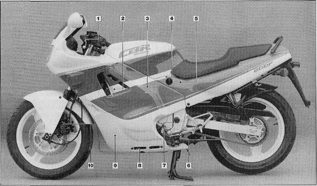
Component locations on CBR600 left side
- Clutch cable upper adjuster
- Valves, spark plugs
- Carburettors
- Fuel tap filter
- Fuel in-line filter
- Drive chain
- Drive chain slider
- Engine oil drain bolt
- Oil filter
- Brake pads
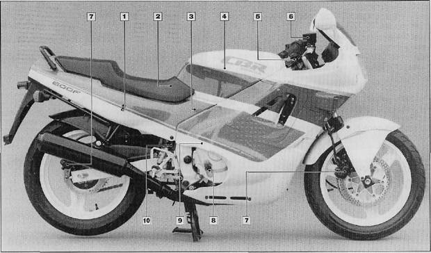
Component locations on CBR600 right side
- Rear brake fluid reservoir
- Battery
- Coolant tank
- Air cleaner
- Steering head bearings
- Front brake fluid reservoir
- Brake pads
- Engine oil filler
- Clutch cable lower adjuster
- Rear brake light switch
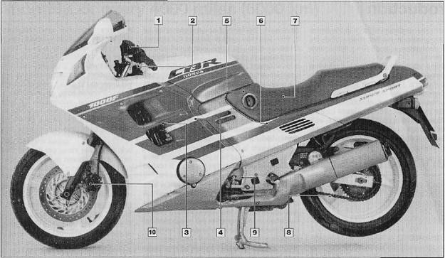
Component locations on CBR1000 left side
- Clutch fluid reservoir
- Steering head bearings
- Valves, spark plugs
- Carburettors
- Fuel tap filter
- In-line fuel filter (early models)
- Battery
- Drive chain
- Drive chain slider
- Brake pads
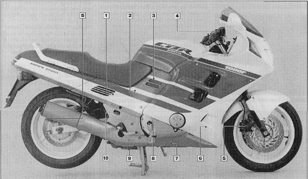
Component locations on CBR1000 right side
- Rear brake fluid reservoir
- Coolant tank
- Air cleaner
- Front brake fluid reservoir
- Brake pads
- Engine oil drain bolt
- Engine oil filler
- Engine oil filter
- Crankcase breather hose plug
- Rear brake light switch
Introduction
- This Chapter is designed to help the home mechanic maintain his/her motorcycle for safety, economy, long life and peak performance.
- Deciding where to start or plug into the routine maintenance schedule depends on several factors. If you have a motorcycle whose warranty has recently expired, and if it has been maintained according to the warranty standards, you may want to pick up routine maintenance as it coincides with the next mileage or calendar interval. If you have owned the machine for some time but have never performed any maintenance on it, then you may want to start at the nearest interval and include some additional procedures to ensure that nothing important is overlooked. If you have just had a major engine overhaul, then you may want to start the maintenance routine from the beginning. If you have a used machine and have no knowledge of its history or maintenance record, you may desire to combine all the checks into one large service initially and then settle into the maintenance schedule prescribed.
- Before beginning any maintenance or repair, the machine should be cleaned thoroughly, especially around the oil filter, spark plugs, cylinder head cover, sidepanels, carburettors, etc. Cleaning will help ensure that dirt does not contaminate the engine and will allow you to detect wear and damage that could otherwise easily go unnoticed.
- Maintenance information is printed on decals attached to the motorcycle. If the information on the decals differs from that included here, use the information on the decal.
Every 600 miles (1000 km)
1. Drive chain - adjustment and lubrication

Adjustment
- To check the drive chain freepiay, place the machine on its centrestand with the rear wheel clear of the ground. Find the chain's tightest spot by rotating the rear wheel and feeling the amount of freepiay present on the bottom run of the chain, testing along the complete length of the chain. When the tightest spot has been found, push the machine off its centre stand and support it on the side stand. Measure the total up and down movement available on the bottom run of the chain midway between the sprockets (see illustration). This measurement should be within the limits given in the Specifications. If not the chain must be adjusted as follows.
- Slacken the rear axle nut and loosen the chain adjuster locknuts. Tighten both adjuster nuts by an equal amount to draw the axle back until the drive chain freepiay is correct (see illustration).
- To preserve accurate wheel alignment, ensure that the same amount of lines (cast on the surface of each adjuster) are visible in the cutout of each swingarm fork end on both sides of the machine. A more accurate check of wheel alignment can be made by laying a plank of wood or drawing a length of string parallel to the machine so that it touches both walls of the rear tyre. Wheel alignment is correct when the plank or string is equidistant from both walls of the front tyre when tested on both sides of the machine (see illustration).
- Once wheel alignment is known to be correct, tighten the axle nut to the specified torque setting followed by the adjuster locknuts. Place the machine on its centre stand and check that the wheel spins freely.
- Take note of the chain wear indicator labels on the swingarm ends and renew the chain if the arrowed alignment mark comes into the red 'replace chain' zone.
Lubrication
- Although the chain fitted as standard equipment is of the O-ring type, grease being sealed into the internal bearing surfaces by O- rings at each end of the rollers, lubrication is still required to prevent the rollers from wearing on the sprocket teeth and to prevent the O-rings from drying up. A heavy (SAE 90) gear oil is best for this task; it will stay on the rollers longer than a lighter engine oil.
- Whilst spinning the rear wheel, allow oil to dribble onto the rollers until all are oily, then apply a small amount to the O-rings on each side (see illustration). An alternative is to use one of the proprietary aerosol-applied chain lubricants.
Caution: Some propellants used in aerosols cause the O-rings to deteriorate very rapidly, so matte certain that the product is marked as being suitable for use with O-ring type chains (see illustration).
HAYNESS HINT Apply oil to the top of the lower chain run - centrifugal force will work it into the chain when the bike is moving.

1.1. Measuring final drive chain freeplay

1.2. Rotate chain adjuster nuts by an equal amount

1.3. Method of checking wheel alignment: A and C incorrect, B correct

1.7. Lubricating the final drive chain
Six monthly, or every 4000 miles (6000 km)
2. Spark plugs – check

-
On 1000 H and J models remove both the upper fairing inner covers and left and right sidepanels. On 1000 K models onward remove the seat. On all 1000 models remove the fuel tank front mounting bolts then raise the tank up and support it on its prop stay. On 600 models remove both the left and right side covers from the fairing.
- Carefully pull off the spark plug caps and remove any dirt or other foreign matter from the spark plug channels. Using a suitable plug spanner, unscrew and remove the spark plugs whilst keeping them clearly defined by their cylinder number.
- Using feeler gauges, preferably of the wire type for greater accuracy, measure the gap between the electrodes and compare it with the figure given in the Specifications. If adjustment is required this can be carried out as described below, assuming that the plug is otherwise undamaged. In the event that any plug is heavily fouled or damaged in any way renewal is required; renew the plugs as a set. Note: Ensure that the plugs are of the resistor type (indicated by the letter H) to ensure compliance with the ignition system. The same applies to the suppressor caps it these are ever renewed.
- If the spark plugs are still serviceable, carefully compare the appearance of their electrodes with the colour photographs at the end of this manual and note any information obtained from this. If any plug appears to show a fault, seek expert advice as soon as possible. The standard grade of spark plug should prove adequate in normal use and a change of specification (such as fitting a hotter or colder grade of plug) should not be made without expert advice from a Honda dealer.
- Clean the plug electrodes by carefully scraping away the accumulated carbon deposits using a small knife blade or small files and abrasive paper; take care not to bend the centre electrode or to chip or damage the ceramic insulator. Caution: The cleaning of sparkplugs on commercial sand-blasting equipment is not recommended due to the risk of abrasive particles being jammed in the gap between the insulator and plug metal body, only to fall clear later and drop into the engine; any plug that is too heavily fouled should be renewed.
- Once clean, file the opposing faces of the electrodes flat using a small fine file. A magneto file or even a nail file is ideal for this purpose. Whichever method is chosen, make sure that every trace of abrasive and loose carbon is removed before the plug is installed. If this is not done, the debris will enter the engine and cause damage or rapid wear.
- Whether a cleaned or new plug is fitted, always check the electrode gap before installing it. Use a spark plug adjusting tool or feeler gauges to measure the gap, and if adjustment is required, bend the outer (earth) electrode only. Note: Never bend the centre electrode or the ceramic insulator nose will be damaged.
- Before the plugs are fitted, apply a fine coat of PBC or molybdenum disulphide grease to their threads. This will help prevent thread wear and damage on installation, and make their subsequent removal easier. Fit each plug finger-tight, then tighten it by a further 1/4 turn only, to ensure a gas-tight seal. Beware of overtightening, and always use a plug spanner or socket of the correct size; tighten all spark plugs to the specified torque setting, where possible.
- Never overtighten a spark plug otherwise there is a risk of stripping the thread from the cylinder head, especially as it is cast in light alloy. A stripped thread can be repaired without having to scrap the cylinder head by using a Helicoil wire thread insert. This is a low-cost service, operated by a number of dealers.
- When refitting the suppressor caps, ensure that the HT leads are correctly routed; note that the leads are numbered as an aid to identification.
3. Air cleaner element – cleaning

-
On 600 models remove the fuel tank as described in Chapter 4. Slacken the screws which retain the top of the air cleaner housing, lift off the cover and remove the element (see illustrations). On 1000 models remove the right sidepanel then slacken the three screws which retain the air cleaner housing side cover, removing it from the machine {see illustration). Pull out the retaining clip from the bottom of the element and withdraw the element from the housing (see illustrations).
- The element is of the dry paper type and can be cleaned by gently tapping the element on a solid surface to dislodge the dust and debris from the paper. If compressed air is available, use it to clean the element by blowing from the inside out. If the paper is extremely dirty or torn, the element must be renewed. Note: On 1000 models drain the crankcase breather tube, as described in the following Section, before refitting the element.
- The element is installed by a reverse of the removal process. On 600 models note that the element must be installed so that the arrow on its frame is on the top surface, facing forwards (see illustration). Ensure the element is correctly seated then refit the top of the air cleaner housing, tighten its retaining screws securely. Refit the fuel tank as described in Chapter 4. On 1000 models ensure the element is correctly positioned in the housing and secure it in place with its retaining clip. Refit the side cover to the air filter housing, ensuring it is correctly seated, and tighten its retaining screws securely. Refit the sidepanel.
- It is essential that the element and housing sections or covers are correctly positioned and seat well to prevent unfiltered air entering and damaging the engine. The carburettors are also jetted to compensate for the presence of the element; if it is damaged, severely blocked or bypassed in any way or omitted, serious engine damage could result. Owners of US machines should also note that the air cleaner is subject to the anti-tampering legislation currently in force (see Chapter 4). For this reason the engine should never be run with the air cleaner element removed or disconnected.

3.1a On 600 models remove air cleaner housing top screws, remove cover...

3.1 b ... and air cleaner element

3.1c On 1000 models remove the air cleaner right side cover...

3.1d ... withdraw the element retaining clip...

3.1 e ... and remove the element

3.3 On 600 models ensure arrow on element is facing forward
Every 4000 miles (6000 km)
4. Crankcase breather - draining (1000 models)

Note: In addition to the service interval, the crankcase breather should be cleaned whenever the machine is ridden hard in wet conditions or washed. It must also be drained whenever deposits can be seen in the transparent section of the breather tube.
1. The crankcase breather tube can be found on the underside of the machine, just behind the centre stand. The tube is connected to the air cleaner housing and is used to drain any water or oil present in the housing.
2. To drain the tube simply remove the plug from its end and allow the contents to drain out into a suitable container (see illustration). When draining is complete refit the plug.

4.2 On 1000 models remove the crankcase breather drain plug and allow its contents to drain
5. Engine idle speed – check

1. The idle speed should be checked and adjusted before and after the carburettors are synchronised and when it is obviously too high or too low. Before adjusting the idle speed, make sure the valve clearances and spark plug gaps are correct. Also, turn the handlebars back-and-forth and see if the idle speed changes as this is done, if it does, the throttle cable may not be adjusted correctly, or it may be worn out. This is a dangerous condition that can cause loss of control of the bike. Be sure to correct this problem before proceeding.
2. The engine should be at normal operating temperature, which is usually reached after 10 to 15 minutes of stop and go riding. Place the motorcycle on the centrestand and make sure the transmission is in Neutral.
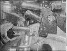
3. Turn the throttle stop screw (see illustration), until the idle speed listed in this Chapter's Specifications is obtained.
4. Snap the throttle open and shut a few times, then recheck the idle speed. If necessary, repeat the adjustment procedure.
5. If a smooth, steady idle can't be achieved, the fuel/air mixture may be incorrect. Refer to Chapter 4 for additional carburettor information.

5.3 Idle speed adjustment on 1000 models
6. Battery – checks

600 models
1. This model has a sealed battery, and thus requires no maintenance with regard to topping-up its electrolyte. All that should be done is to check that its terminals are clean and tight and that the casing is not damaged or electrolyte leaking. If the battery does need to be removed for any reason, refer to Chapter 8, Section 3 for details.
1000 models
2. Remove the seat then unhook the rubber strap and remove the battery cover and the tool kit. Remove the battery by disconnecting the leads and lifting it out of the machine. Note: Always disconnect the negative (-) terminal first when disconnecting the battery terminals to prevent the risk of short circuits.
3. The electrolyte level, visible through the translucent casing, should be between the two level marks on the battery casing. If not, remove the ceil caps and top up to the upper level mark using only distilled water (see illustration).
4. Check the battery for any signs of pale grey sediment at the bottom of the casing. This is caused by sulphation of the plates due to recharging at too high a rate or as a result of the battery being left discharged for long periods. A good battery should have little or no sediment visible and its plates should be straight and pale grey or brown in colour. If sediment deposits are deep enough to reach the bottom of the plates, or if the plates are buckled and have whitish deposits on them, the battery is faulty and must be renewed. Remember that a poor battery will give rise to a large number of minor electrical faults.
5. On installation, check that the battery breather hose is not blocked and is correctly routed. Connect up the battery terminals, remembering to connect the negative (-) terminal last. Ensure that the terminals are tight and that the rubber cover is correctly fitted to the positive (+} terminal. Put the tool kit and cover back in place and secure the cover in position with the rubber strap.

6.3 On 1000 models electrolyte level must be between marks on casing
All models
6. If the machine is not in regular use, disconnect the battery and give it a refresher charge every month to six weeks, as described in Chapter 8.
HAYNES HINT Battery terminal corrosion can be minimised by applying a layer of petroleum jelly to the terminals after the leads have been connected.
7. Brake pads - wear check

 Warning: Brake pads contain asbestos. Take great care not to inhale any brake dust during the operation, and read the notes given in Safety first! concerning asbestos. Warning: Brake pads contain asbestos. Take great care not to inhale any brake dust during the operation, and read the notes given in Safety first! concerning asbestos.
1. The brake pads can be checked for wear without removing them from the caliper. On 600 models they can be checked through the gap between the caliper and bracket which is indicated by the cast arrow on the caliper surface. On 1000 models the front pads can be checked from the underside of the caliper, and the rear pads from the rear of the caliper.
2. On all models, the need for brake pad renewal can be determined by referring to the pad wear indicator on the friction material. Depending on the pad's manufacture, the wear limit indicator will be shown either as a series of grooves cut into the friction material, which will be visible until the pads have worn down to the bottom of the grooves, or as a wear groove or chamfer on the backing metal side of the pad, the wear limit being when the friction material wears to the point where the groove or chamfer is exposed.
3. Due to the different types of pad fitted, it is recommended that the pad type be determined as soon as possible, before renewal becomes necessary. If there is any doubt about the pads' condition or if identifi cation of pad type is difficult with the pads installed in the calipers, remove them as described below. If renewal is necessary, always renew both pads as a set, and in the case of the front brake, renew both sets at the same time.
Front brake - 1000 H, J and all 600 models
4. Remove both plugs from the caliper to reveal the pad pin retaining bolt heads; slacken both pad pins. Slacken and remove the caliper bracket mounting bolts and slide the caliper off the disc, taking care not to place any undue strain on the hydraulic hose. Remove both pad pins from the caliper and withdraw the brake pads, noting the correct position of the pad spring fitted to the caliper body.
5. Inspect the surface of each pad for contamination and check that the friction material has not worn beyond its service limit groove. If either pad is worn to or beyond the service limit at any point, fouled with oil or grease, or heavily scored or damaged by dirt and debris, both pads must be renewed as a set. Note that it is not possible to degrease the friction material; if the pads are contaminated in any way they must be renewed.
6. If the pads are in good condition clean them carefully, using a fine wire brush which is completely free of oil or grease, to remove all traces of road dirt and corrosion. Using a pointed instrument, clean out the grooves in the friction material and dig out any embedded particles of foreign matter {as applicable). Any areas of glazing may be removed using emery cloth.
7. Ensure that the pad spring is correctly positioned in the caliper and remove all traces of corrosion from the pad retaining pins. Push the pistons as far back into the caliper as possible using hand pressure only; this is especially important if new pads are being fitted, due to the increased friction material thickness. Insert the pads into the caliper, and install the pad retaining pins, ensuring that they pass through both pads correctly (see illustrations).
8. Slide the caliper assembly onto the disc and refit the caliper bracket mounting bolts, tightening them to the specified torque setting (see illustration). Note: The bottom left caliper bracket mounting bolt is also the anti- dive pin and should only be tightened to a torque setting of 1.2 kgf m (9 Ibf ft). Tighten the pad retaining pins to the specified torque setting and refit the pad pin plugs, tightening them securely (see illustration).

7.7a On 1000 H, J and all 600 models position front brake pad spring in caliper...

7.7b ... install brake pads ...

7.7c ... and refit pad retaining pins

7.8a Install caliper and tighten caliper mounting bolts ...

7.8b ... and pad retaining pins to specified torque setting. Do not omit pad pin plugs
Rear brake - 1000 H, J and all 600 models
9. Slacken the pad pin retaining plate bolt and remove the plate tram the caliper. Remove the caliper mounting bolt and rotate the caliper in a clockwise direction until it is clear of the disc. The caliper can then be removed from the machine by pulling it away from the wheel to free it from its mounting bracket, taking care not to place any undue strain on the brake hose. The pad pins can then be pulled out of the caliper using a pair of pointed-nose pliers, and the pads withdrawn, noting the correct position of the pad retaining spring in the caliper.
10. Inspect the pads as described above in paragraphs 5 and 6. Install the pads in the caliper as described in paragraph 7 before fitting the caliper as follows.
11. Remove all traces of corrosion from the caliper mounting pin then smear a small amount of silicone grease along its length. Refit the caliper to the mounting bracket, then swing the caliper down into position ensuring that the pads are positioned correctly on each side of the disc (see illustration). Install the caliper mounting bolt, having first smeared silicone grease along its shank, and tighten it to the specified torque setting (see illustration). Fit the pad pin retaining plate ensuring that it engages correctly with the slots in the pad pins and tighten its bolt to the specified torque setting (see illustration).

7.11a On 1000 H, J and all 600 models rear brake locate caliper pin with mounting bracket...

7.11b ... then swing caliper down onto disc and insert its mounting bolt

7.11c Ensure the pad pin retaining plate engages correctly with the pins and refit its retaining bolt

7.14a On 1000 K, L, M, N models slide pads into caliper

7.14b Refit pad retaining pin…

7.14c ... followed by pad pin plug

7.15a Unscrew the pad retaining pin

7.15b ... and press the spring plate on the inside of the caliper to release the pad retaining pin

7.15c Withdraw the pads from the caliper
Front and rear brake - 1000 K, L, M and N models
12. The brake pads on these models can be removed and Installed whilst the caliper is fitted to the machine. Remove the pad pin plug from the caliper and slacken the pad retaining pin. Withdraw the pad retaining pin and slide the brake pads out of the caliper.
13. Inspect the pads as described above in paragraphs 5 and 6.
14. Check that the pad spring is in place in the caliper. Slide the pads into position ensuring that they locate correctly with the caliper mounting bracket, and refit the pad retaining pin (see illustrations). Note: If new pads are installed, it will first be necessary to push the pistons back into the caliper to gain the necessary clearance for the increased friction material thickness. Tighten the pad retaining pin to the specified torque setting and refit the pad pin plug, tightening it securely (see illustration).
Front and rear brake - 1000 P models onward
15. The brake pads can be removed and installed with the caliper fitted to the machine. Unscrew the pad retaining pin and press the spring plate on the other side of the caliper to allow the retaining pin to be withdrawn (see illustrations). Slide the brake pads out of the caliper (see illustration).
16. Inspect the pads as described above in paragraphs 5 and 6.
17. Check that the pad spring is in place in the caliper. Slide the pads into the caliper ensuring that they locate correctly with the plate on the caliper mounting bracket (see illustration). Note: If new pads are installed, it will first be necessary to push the pistons back into the caliper to gain the necessary clearance for the increased friction material thickness. Slide the pad retaining pin into position so that it passes through the holes in each pad and check that the spring clip engages its end. Tighten the pad retaining pin the specified torque setting.
All models
18. Pump the brake lever or pedal (as applicable) repeatedly until the pads are pushed back against the disc(s) and normal operation of the brake has returned. Check the fluid level in the reservoir as described in "Daily (pre-ride) checks", noting that if new brake pads have been fitted it may be necessary to remove fluid from the reservoir.
19. Check the hydraulic system for leaks and ensure that the braking system is operating correctly. Remember that new pads, and to a lesser extent, cleaned pads will not function at peak efficiency until they have bedded in. Where new pads have been fitted, use the brake firmly but gently for the first 50 - 100 miles.

7.17 As the pads are inserted, ensure they engage the plate on the caliper mounting bracket (arrowed)
8. Clutch - check (600 models)

1. Check that the clutch cable operates smoothly and easily. If the clutch lever operation is heavy or stiff, lubricate the cable as described in the following Section. When the cable is operating smoothly it is necessary to check that the clutch lever is correctly adjusted. The clutch is correctly adjusted when there is 10 - 20 mm (0.4 - 0.8 in) freeplay, measured at the ball end of the I ever (see illustration). If adjustment is required, use the handlebar end adjuster on the lever mounting bracket (see illustration).
2. If there is insufficient range in the upper adjuster it will be necessary to remove the right side cover from the fairing and adjust the freeplay at the lower adjuster on the casing (see illustration). Screw the upper adjuster fully inwards and slacken the locknut on the lower adjuster. Rotate the adjuster nut until the required freeplay is obtained at the handlebar lever, then securely tighten the lower adjuster locknut and refit the side cover to the fairing. If necessary, fine adjustments can then be made using the handlebar adjuster.

8.1 a Clutch cable freeplay is measured at lever end - 600 models
8.1 b Adjust clutch cable freeplay using upper...

8.2 ... and lower adjusters
9. Control cables and pivot points - lubrication

Control cables
1. Check the outer cables for signs of damage, then inspect the exposed portions of the inner cables. Any signs of kinking or fraying will indicate that renewal is required. To obtain maximum life and reliability from the cables they should be thoroughly lubricated.
2. To lubricate the throttle, choke and clutch (600 models) cables, disconnect each cable at its lower end, then lubricate the cable with a pressure lube adapter (see illustration). An alternative is to remove the cable from the machine, hang the cable upright, and make a small funnel arrangement using plasticine or by tapping a plastic bag around the upper end of the cable (see illustration). Fill the funnel with oil and leave it overnight to drain through
3. The speedometer cable should be removed for examination and lubrication as described in Chapter 6.

9.2a Lubricating a cable with a pressure lube adapter (make sure the tool seats around the inner cable)
Pivot points
4. The footpegs, clutch and brake levers, brake pedal, gearshift lever and side and centrestand pivots should be lubricated frequently. If the pivot is particularly dry, the component should be disassembled for thorough lubrication. However, if chain and cable lubricant is being used, it can be applied to the pivot joint gaps and will usually work its way into the areas where friction occurs. If motor oil or light grease is being used, apply it sparingly as it may attract dirt (which could cause the controls to bind or wear at an accelerated rate). Note: One of the best lubricants for the control lever pivots is a dry-film lubricant (available from many sources by different names).
5. Check that the stands are held securely in their raised positions by the return springs.

9.2b Lubricating a control cable using a funnel type arrangement
Annually, or every 8000 miles (12,000 km)
10. Engine/transmission oil and filter - change

Note: The oil should be drained from the engine whilst it is at its normal operating temperature. This ensures that the oil is relatively thin and will therefore drain quicker and more completely, also any impurities will be held in suspension.
1. Remove the fairing side sections, noting that on 1000 H and J models it is only necessary to remove the lower section (see Chapter 6).
2. On all models, start the engine and warm it up to normal operating temperature. Place machine on its centrestand on level ground and position a suitably-sized container, of at least 4.5 litres (4.8 US qt, 8.0 Imp pt) capacity, beneath the engine unit and remove the drain plug from the sump (see illustration). Remove the oil filler cap to assist draining.

Warning: Take great care to scalding your hands on the escaping oil or on the exhaust system.

10.2 Engine oil drain plug location - 600 models
3. Oil filter removal is easy if access to the Honda service tool, Part Number 07HAA-PJ70100, can be obtained. This tool is a socket spanner which fits over the end of the filter allowing it to be removed using a ratchet. If this tool cannot be obtained the filter must be slackened using a strap spanner, although its use will be awkward and great care must be taken to avoid burning your hands on the exhaust system. Discard the filter.

10.4 Apply oil to filter O-ring prior to installation
4. Check the condition of the drain plug sealing washer, renewing it if necessary, and refit the drain plug to the sump. Apply a small amount of oil to O-ring of the new oil filter and screw the filter onto the crankcase (see illustration). Tighten the drain plug, and if possible, the oil filter to their specified torque settings.
5. Fill the crankcase with the specified amount and grade of oil. Refit the filler cap and start the engine, allowing it to idle for a few minutes to distribute the new oil through the lubrication system. Switch off the engine and wait a few minutes to allow the oil level to settle. Check the oil level as described in "Daily (pre-ride) checks" and adjust as necessary.
6. The old oil drained from the engine cannot be reused in its present state and should be disposed of. Check with your local refuse disposal company, disposal facility or environmental agency to see whether they will accept the used oil for recycling. Don't pour used oil into drains or onto the ground.

Note: It is antisocial and illegal to dump oil down the drain. To find the location of your local oil recycling bank, call this number free.
In the USA, note that any oil supplier must accept used oil for recycling.
HAYNES HINT Check the old oil carefully. If the oil was drained into a clean pan, small pieces of metal or other material can be easily detected. If the oil is very metallic coloured, then the engine is experiencing wear from break-in (new engine) or from insufficient lubrication. If there are flakes or chips of metal in the oil, then something is drastically wrong internally and the engine will have to be disassembled for inspection and repair. If there are pieces of fibre-like material in the oil, the clutch is experiencing excessive wear and should be checked.
11. Valve clearances- check

Note: The valve clearances must be checked and adjusted with the engine cold, preferably after the machine has been left overnight.
1. Remove the cylinder head cover as described in Chapter 2, Section 7. On 600 models remove the crankshaft and timing hole caps from the right crankcase cover. On 1000 models remove the cap from the left crankshaft end cover, noting that on 1000 K models onward it will first be necessary to remove the engine protector (see illustration).
2. Using a suitable socket on the large hexagon nut on the end of the crank, turn the crankshaft in a clockwise direction on 600 models and an anticlockwise direction on 1000 models, until the T mark on the flywheel or crankcase aligns with the index mark visible on the crankcase cover or rotor (as applicable) and number 4 cylinder is at TDC on its compression stroke (if inlet valve has just closed) (see illustration).
3. With the engine in this position check the inlet valve clearances of number 2 and 4 cylinders and the exhaust valve clearances of cylinders 3 and 4. Using feeler gauges, measure the clearance between the follower and cam lobe. Turn the crankshaft through one complete turn (360°) so that number 1 cylinder is at TDC on its compression stroke, and check the inlet clearances of numbers 1 and 3 cylinders and the exhaust valve clearances on cylinders 1 and 2. All clearances must be within the specified limits given in the Specifications. If any are less than specified, action must be taken immediately to prevent damage to the valve and valve seat. If any are larger than specified the error must still be corrected but the problem is not quite as serious. If necessary, the clearances can be adjusted as described below using the screw and locknuts fitted to the cam followers.
4. On 1000 H, J and all 600 models the task of adjusting the valve clearances will be made considerably easier using the Honda locknut and adjusting screw wrenches, Part Numbers 07GMA-ML70120 and 07GMA-ML70110 respectively. On 1000 K models onward the clearances are adjusted using the aforementioned locknut spanner together with a modified 3 mm Allen key, cut to 65 - 68 mm (2.56 - 2.58 in) in length.
5. Slacken the locknut and turn the adjuster screw in or out until a feeler gauge of the appropriate size is a light sliding fit between the cam lobe and follower. Hold the screw and tighten the locknut to the specified torque setting. Recheck the clearance after the locknut has been tightened and re-adjust if necessary (see illustration).
6. Once all clearances have been correctly set, turn the crankshaft through several revolutions then recheck all clearances before installing the cylinder head cover as described in Chapter 2. Always record the original and new clearance so that an accurate picture of the valve gear and its rate of wear can be built up.

11.1 On 1000 K models onward remove left engine protector

11.2 Remove crankshaft end cap and set crankshaft to TDC using index marks - 1000 model shown

11.5 Adjusting the valve clearances
12. Spark plugs - renewal (US 1000 L models onwards and all UK models)

1. Refer to Section 2 for details of this procedure.
13. Throttle and choke cable - freeplay check

Throttle cable adjustment
1. There should be 2 - 6 mm (0.08 - 0.24 in) of freeplay in the throttle cables, measured in terms of twistgrip rotation (see illustration). If this is not the case, slacken the locknut on the cable upper adjuster and rotate the adjuster until the required amount of freeplay is obtained then tighten the locknut. If it is not possible to obtain the correct freeplay with the upper adjuster, it will also be necessary to make adjustment at the lower adjuster, situated on the carburettors (see illustration).
2. To gain access to the lower adjuster on 600 models it is necessary to remove the fuel tank as described in Chapter 4, and the air cleaner housing. On 1000 H and J models remove both the upper fairing inner covers and sidepanels, and on K models onward remove the seat. On all 1000 models, remove the fuel tank front mounting bolts, lift the tank up and support it on its prop stay. Screw the upper cable adjuster in to obtain the maximum possible freeplay, then slacken the lower adjuster locknut and set the cable freeplay using first the lower adjuster and then, \' necessary, the upper adjuster. Once the freeplay is correct tighten the locknuts securely (see illustration).
3. Check that the throttle twistgrip operates smoothly and snaps shut quickly when released. Start the engine and allow it to idle, then move the handlebars from lock to lock. If the idle speed rises and falls as the handlebars are turned the throttle cables are incorrectly routed. To remedy, remove the retaining screws from the right handlebar switch and separate the two halves of the switch. Disconnect the cables from the twistgrip and re-route them along the smoothest possible route, ensuring that they are not kinked or foul any other component. Before connecting the cables lubricate them as described in Section 9, then reconnect the cables and check the freeplay, adjusting again if necessary.
Choke cable adjustment
4. Remove or raise the fuel tank as described in paragraph 3. Operate the handlebar mounted lever whilst observing the movement of the choke mechanism. The mechanism should extend smoothly when the lever is pulled, and return home fully when the lever is returned. If the choke mechanism does not operate smoothly this is probably due to a cable fault. Remove the retaining screws from the left handlebar switch and disconnect the cable at its upper end. Re-route the cable so it takes the smoothest route possible and lubricate it as described in Section 9. Reconnect the cable and tighten the handlebar switch screws securely. If this fails to improve the operation of the choke the cable must be renewed. Note that in very rare cases the fault could lie in the carburettors rather than the cable, necessitating the removal of the carburettors and examination of the choke plungers as described in Chapter 4.
5. Once the choke mechanism is operating smoothly it is necessary to ensure that there is a small amount of freeplay on the choke cable. It is recommended that there should be approximately 2 - 3 mm (0.08 - 0.12 in) of lever travel, measured at the base of the lever, before the mechanism starts to move. To adjust the cable, slacken the choke cable clamping screw, situated on the carburettors, then move the lower end of the cable until the required amount of freeplay is obtained. Tighten the clamping screw securely (see illustration).

13.1 a Throttle cable freeplay is measured in terms of twistgrip rotation at the grip flange (arrowed)

13.1b Adjust throttle cable freeplay using the upper...

13.2 ... and, if necessary, lower cable adjusters - 600 shown

13.5 Loosen cable retaining clamp to set choke cable freeplay
14. Carburettors – synchronization

Note: A set of accurate vacuum gauges is essential for synchronising the carburettors; if not available, the job should be entrusted to a Honda dealer. On no account attempt to adjust synchronisation by feel - it will almost certainly make things worse.
Note: The carburettors must be synchronised with the engine at its normal operating temperature and the machine on its centrestand.
1. Before the carburettors can be synchronised, ensure that the throttle and choke mechanisms are operating correctly (see Section 13).
2. On 600 models, remove the fuel tank, as described in Chapter 4, and the left and right side fairings. Slacken and remove the four screws, one in each inlet tract, from the cylinder head and screw in the adapters. Connect the vacuum gauge hoses to the relevant adapters and arrange a temporary fuel supply, either by using a small temporary tank or by using extra long fuel pipes to the now remote fuel tank on a nearby bench.
3. On all 1000 models raise the fuel tank up and support it on its prop stay. On 1000 H, J, K, L, M, N models, remove the rubber plug or vacuum tube (as applicable) from the vacuum take-off point on the top of each carburettor and connect the vacuum gauge hoses to the take-off points (see illustration). On 1000 P models onward, release the fuel tap vacuum hose from No. 1 cylinder take-off point, the rubber plugs from Nos. 2 and 3 cylinder take off points, and the screw and washer from No. 4 cylinder take-off point. Screw an adapter into No. 4 take-off point and connect the vacuum gauge hoses (see illustration).
4. On all models, start the engine and allow it to warm up to normal operating temperature. If the gauges are fitted with damping adjustment, set this so that the needle flutter is just eliminated but so that they can still respond to small changes in pressure. Set the engine to the specified idle speed.
5. With the engine idling, check that all needles produce the same reading. A tolerance of 2 cm Hg on 1000 models and 4 cm Hg on 600 models is permissible but it is better to have all cylinders adjusted to the same reading; this is by no means as difficult as it would appear, requiring only a little care and patience. Note that it does not matter what the reading is, only that it is the same for all four cylinders. Stop the engine and allow it to cool down if it overheats.
The carburettors are adjusted by the three screws situated between each carburettor, in the throttle linkage (see illustrations). Number two cylinder (all 600 models and 1000 H, J, K, L, M, N models) or number three cylinder (1000 P models onward) carburettor should be used as the base setting and the other three carburettors should be adjusted to the same. Note: Do not press down on the screws whilst adjusting them, otherwise a false reading will be obtained. When all the carburettors are synchronised, open and close the throttle quickly to settle the linkage, and recheck the gauge readings, readjusting if necessary.
When all the carburettors are correctly synchronised, stop the engine, disconnect the gauges and remove the adapters (as applicable). Refit all the disturbed components. On 600 models (and No. 4 cylinder on 1000 P models onward) check the condition of the sealing washers fitted to the inlet tract screws, renewing them if necessary, and ensure the screws are tightened securely.

14.3a Vacuum take off point -1000 H, J, K, L, M, N models

14.3b Vacuum take off point with gauge adapter in position -1000 P models onward

14.6a Carburettor synchronising screw positions (x) - 600 models

14.6b Carburettor synchronising screw positions (x) -1000 models
15. Clutch - check (1000 models)

1. Check the fluid level as described in Daily (pre-ride) checks.
2. Inspect the clutch hose for signs of leakage or deterioration, especially at the unions on the master cylinder and slave cylinder.
3. If there are traces of air in the system, the clutch should be bled as described in Chapter 7 using the procedure given for bleeding air from the hydraulic brake system.
16. Fuel pipe and fitters - inspection

 Warning: Petrol (gasoline) is extremely flammable, especially when in the form of vapour. Take all precautions to prevent the risk of fire and read through Section 3 of Chapter 4 and the Safety first! Section of this Manual before carrying out the following operation. Warning: Petrol (gasoline) is extremely flammable, especially when in the form of vapour. Take all precautions to prevent the risk of fire and read through Section 3 of Chapter 4 and the Safety first! Section of this Manual before carrying out the following operation.
1. The fuel system hoses should be inspected for signs of damage and checked for security as described in Section 6 of Chapter 4.
2. The fuel tap should be removed from the machine and its fuel filter cleaned as described in Section 5 of Chapter 4 (see illustration).
3. On 600 and 1000 H and J models remove the sidepanel and inspect the fuel pump filter for signs of clogging. If there are any traces of debris visible through the translucent material of the filter, the filter must be renewed. Note: The new filter must be installed with the arrow on the filter body pointing towards the outlet (fuel pump) side of the filter (see illustration).

16.2 Remove the fuel tap and clean its filter

16.3 Ensure fuel pump filter is installed so that arrow faces pump
17. Cooling system -checks

1. With reference to Chapter 3, check the cooling system for leakage and damaged components. Pay particular attention to the hoses and check that all hose clips are correctly positioned and securely fastened.
2. Check the drainage hole on the underside of the water pump body for signs of leakage. Leakage from this hole indicates failure of the pump's mechanical seal.
18. Secondary air supply system - check (California models)

Note: The air supply system is subject to anti-tampering legislation currently in force which means that the machine must never be used with any part of the system disconnected, missing, rendered inoperative or modified in any way.
1. Remove the necessary bodywork and check all the air supply system hoses for damage and deterioration, paying particular attention to the areas around the hose clips. Ensure that none of the hoses are kinked, pinched or split. If the renewal of any component is required use only genuine Honda replacement parts.
2. Refer to the vacuum hose routing label stuck to the air cleaner cover.
19. Steering and suspension - checks and adjustment

Checks
1. Place the machine on its centre stand and raise the front wheel clear of the ground using a suitable stand. Check the steering head bearings by grasping the bottom of both fork sliders, then pulling and pushing in a fore and aft direction; any freeplay should be felt between the fork bottom triple clamp (yoke) and the frame head lug. Check for overtightened bearings by placing the forks in a straightahead position and tapping lightly on one handlebar end; the forks should fall away smoothly and easily to the opposite lock, taking into account the effect of cables and wiring, with no traces of notchiness. If necessary, adjust the steering head bearings using the information in Chapter 6.
HAYNES HINT Freeplay in the fork due to worn fork bushes can be misinterpreted for steering head bearing play - do not confuse the two.
2. Ensure that the front forks work smoothly and progressively by pumping them up and down whilst the front brake is held on. Any faults revealed by this check should be investigated immediately; refer to Chapter 6, particularly if the oil seals are leaking.
3. Check that all the rear suspension pivot bolts are secure and that the pivots operate smoothly. With the machine placed on its centre stand and the rear wheel clear of the ground, check for freeplay in the swingarm by grasping its forked ends and pushing and pulling it horizontally. If freeplay is found, the swingarm or suspension linkage they must be removed and examined as described in Chapter 6.
Front fork adjustment
4. All 600 models and 1000 H, J models feature air-assisted front forks. Note: When checking the air pressures do not use a tyre pressure gauge as they are not accurate enough and lose too much air when disconnected. A special suspension pressure gauge will be needed. When adding air to the front forks. Never use an air line, because these operate at far too high a pressure and could damage the seats, It is recommended that only a bicycle pump or one of the specialist aftermarket kits is used to add air; the latter usually comes equipped with its own built in gauge and is extremely accurate in use.
5. When checking the air pressure raise the front wheel clear of the ground to prevent the pressure in the fork being artificially increased due to the weight of the machine. To achieve this it will be necessary to place the machine on its centre stand and place a suitable sized block beneath the engine. Remove the cap from the top of each fork leg and check the pressure in both legs (see illustration). The recommended pressure range is 0 - 6 psi (0 -0.4 kg/cm2). Low air pressure settings provide a softer ride for light loads and smooth roads and high air pressure settings will provide a firmer ride for heavier loads and rougher road conditions. Note: On no account must the pressure in the fork legs ever exceed 42 psi (3 kg/cm2) as this will almost certainly damage the fork seals. Ensure that the pressure is equal in both legs and refit the caps to the top of the fork legs.
Rear shock absorber adjustment
600 models
6. On all 600 models the rear shock absorber has a 7-position spring preload adjuster fitted to the lower end of the unit. Position 1 is the softest setting through to position 7 which is the hardest. To adjust, remove the left sidepanel, and turn the preload adjuster to the required position using the C-spanner supplied in the machine's tool kit. Looking from the rear of the machine, turning the adjuster clockwise will decrease the preload and turning it anticlockwise will increase the preioad.
7. On 600 L UK models and all US models the shock absorber also has a 3-position damping adjuster. The adjuster takes the form of a thumbwheel situated above the lower mounting bolt. Its position is indicated by the number on its bottom surface which aligns with the index mark on the top surface of the shock absorber. Position 1 is the softest setting and position 3 the hardest. Rotate the adjuster to the required setting ensuring that it clicks into position.
1000 models
8. The rear shock absorber has a 22-position spring preload adjuster. The adjuster is located behind the right sidepanel and can be turned using a suitable socket (see illustration). Turning the adjuster clockwise increases the preload and hardens the ride, and turning it anticlockwise decreases the preload and softens the ride.
9 The shock absorber also features damping adjustment. The 1000 H and J models have a 3-position damping adjuster situated behind the left sidepanel. Its position is indicated by the arrow on the adjuster and the corresponding position on the shock absorber body. Position 1 is the softest setting and position 3 the hardest; position 2 is the standard setting. Set the adjuster to the required position using a suitable screwdriver, ensuring that it clicks into position. On 1000 K models onward the damping adjuster is situated on the lower end of the shock absorber and can be accessed just below the right footpeg (see illustration}. Turn the adjuster clockwise to increase the damping and harden the ride, and anticlockwise to reduce the damping and soften the ride.

19.5 Remove cap to check front fork air pressure

19.8 Adjusting rear suspension spring preload ...

19.9 ... and damping -1000 K models onward
20. Wheels - inspection

1. Check the complete wheel for cracks and chipping, particularly at the spoke roots and the edge of the rirn. As a genera! rule a damaged wheel must be renewed as cracks will cause stress points which may lead to sudden failure under heavy load. Small nicks may be carefully radiused with a fine file and emery paper (No 600 - 1000) to relieve the stress. Note this will destroy the painted finish of the wheel and the wheel will thus require touching in with a suitable paint. If there is any doubt as to the condition of a wheel, advice should be sought from a Honda dealer or specialist wheel repairer.
2. Each wheel is painted to prevent corrosion. If damage occurs to the wheel and the paint is chipped the bared aluminium will soon start to corrode. A whitish grey oxide will form over the damaged area, which in itself is a protective coating. This deposit however, should be removed carefully as soon as possible and the damaged area repainted with a suitable paint.
3. To check the wheel bearings, position the bike on its centrestand with the wheel raised off the ground. Grasp the wheel at the top and bottom and attempt to rock it from side to side about its centre; if freeplay exists the bearings should be replaced (see Chapter 7).
4. Check the lateral runout of the rim by spinning the wheel and placing a fixed pointer close to the rim edge. If the maximum runout exceeds 2.0 mm (0.08 in) axially or radially, Honda recommend that the wheel be renewed. This is, however, a counsel of perfection; a runout somewhat greater than this can probably be accommodated without noticeable effect on the steering or stability of the machine. No means is available for straightening a warped wheel without resorting to the expense of having the wheel skimmed on all faces. If warpage was caused by impact during an accident, the safest measure is to renew the complete wheel.
Note: Worn wheel bearings may cause rim runout; these can be renewed as described in Chapter 7.
5. Note: Impact damage or serious corrosion has wider implications in that it could lead to a loss of pressure from the tubeless tyre. If in any doubt as to the wheel's condition, seek professional advice.
21. Brake system - check

General check - all models
1. Make sure all brake fasteners are tight. Check that the fluid level in the reservoirs is correct (see "Daily (pre-ride) checks"). Look for leaks at the hose connections and check for cracks in the hoses. If the lever or pedal is spongy, bleed the brakes as described in Chapter 7.
Brake light switch check - all models
2. Check that both the front and rear stop lamps are functioning correctly. The front switch is located on the underside of the iever mounting bracket and is not adjustable in any way. If the switch is faulty it must be renewed.
3. The rear stop lamp switch is situated above the rear brake pedal. On 1000 models the switch is accessed through the hole in the sidepanel. To adjust the switch, hold the switch body to prevent it rotating and turn the adjuster nut. The switch should be set so that the stop lamp illuminates just as the rear brake starts to take effect (see illustration).
Dual Combined Brake System (DCBS) check - 1000 P models onward
4. This check must be performed with the motorcycle on its centrestand and the transmission in neutral.
5. Check that the rear tyre is off the ground. Using an 8 mm ring spanner on the left front caliper link bolt, apply a clockwise torque to the bolt and observe the secondary master cylinder pushrod and linkage (see illustration). With the torque applied, the linkage will operate the secondary master cylinder, which will transfer braking force to the outer two pistons of the rear brake caliper, preventing the rear wheel from being rotated. If the link bolt is inadvertently turned anticlockwise and loosens, make sure it is tightened securely. If the rear brake doesn't corne on, there is a problem with the secondary master cylinder or proportional control valve (see Chapter 7 for details).
6. Chock the engine underneath the oil pan (sump) so that the front tyre is off the ground. Depress the rear brake pedal and check that the front wheel will not rotate.

21.3 Adjust rear stop lamp switch as described in text - 600 shown

21.5 Checking the operation of the DCBS -1000 P models onward
22. Drive chain slider - wear check

1. On 1000 models, remove the left sidepanel, followed by the small lower cover.
2. The chain slider is likely to be covered in dirt and excess lubricant from the chain, so clean it first. The nylon chain slider protects the swingarm and chain from direct contact, but will wear down over a period of time. On 1000 P models onward, there is a line and arrow at the head of the slider which determines its wear limit; if the slider has worn down to or beyond the limit line it must be renewed. On ail other models, make a visual check of the slider; if it looks like wearing through soon, renew it.
3. Renewal of the chain slider necessitates removal of the swingarm - refer to Chapter 6 for details.
23. Side stand - check

Side stand checks
1. Check the security of the side stand pivot bolt and check the rubber pad for wear. If the pad has worn down to the wear line, it must be renewed. On 1000 models, if the pad requires renewal, ensure that it is replaced with one marked 'over 260 Ib only'.
2. Ensure that the side stand is securely held in the raised position by its return spring. Honda recommend that spring tension is checked using a spring balance hooked around the rubber pad of the stand. With the stand extended and the weight of the machine off the stand, pull on the spring balance and note the force required to retract the stand. This should be 2 - 3 kg (4.4 - 6.6 Ibs) if the spring is functioning correctly.
Side stand switch check - K models onward
3. Sit on the machine, ensuring the side stand is the raised position. Start the engine, pull the clutch lever in, shift the transmission into first gear and then lower the side stand. As the stand is lowered the engine should cutout. If this is not the case the side stand switch operation is faulty and it should be checked as described in Chapter 5.
4. Lubricate the switch with a water dispersant fluid such as WD40.
24. Headlight aim - check

1. An improperly adjusted headlight may cause problems for oncoming traffic or provide poor, unsafe illumination of the road ahead. Before adjusting the headlight, be sure to consult with local traffic laws and regulations.
2. The headlamp beam aim is set using the adjusters situated on the back of the headlamp unit. To gain access to these adjusters on 1000 H, J and all 600 models it is first necessary to remove the upper fairing inner sections, and on 1000 K models onward it is necessary to remove the maintenance cover from the underside of the upper fairing section (see illustration).
3. On 600 models the knob on the top right of the unit adjusts the horizontal aim of the beam, and the knob on the bottom left alters the vertical aim of the beam. On 1000 H and J models the knob on the top right of the unit alters the vertical aim and the horizontal aim is altered by rotating the bottom left adjuster with a suitable crosshead screwdriver. On 1000 K models onward, each bulb must be adjusted individually. The thumbwheels fitted on each side of the unit adjust the vertical setting of the relevant bulb whilst the horizontal adjusters are positioned in the centre of the unit and are adjusted using a crosshead screwdriver.

24.2 On 1000 K models onward, remove the maintenance cover to gain access to the headlamp adjusters
25. Fasteners - tightness check

1. Work around the machine checking all nuts and bolts for tightness. Pay particular attention to the engine mountings, exhaust mountings, rear suspension and swingarm bolts, top and bottom triple clamp pinch bolts, wheel axles and all brake caliper bolts. Where possible use a torque wrench to check that all fasteners are tightened to their specified torque settings.
Every 18 months, or every 12,000 miles (18,000 km)
26. Air cleaner element - renewal

1. Refer to Section 3 for the air cleaner removal and installation procedure.
27. Evaporative emission control system hoses - check (California models)

Note: The evaporative emission control system is subject to anti'-tampering legislation currently in force which means the machine must never be used with any part of the system disconnected, missing, rendered inoperative or modified in any way.
1. Remove the fuel tank as described in Chapter 4 and inspect all emission control system hoses for signs of damage or deterioration, paying particular attention to the areas around the hose clips. Ensure that none of the hoses are kinked, pinched or split. If the renewal of any component is required use only genuine Honda parts.
2. Refer to the vacuum hose routing label on the air cleaner cover.
Two yearly, or every 12,000 miles (18,000 km)
28. Brake and clutch fluid - renewal

Note: Brake fluid is an excellent paint stripper and will attack painted and plastic components. Wash away any spilt fluid immediately with copious quantities of water.
1. The hydraulic fluid must be renewed at the specified interval to preserve maximum brake/clutch efficiency by ensuring the fluid has not deteriorated to an unsafe level.
2. Before starting work obtain a new, sealed can of the recommended hydraulic fluid (you may need more for the DCBS of the 1000 P models onward) and carefully read the Section on brake bleeding in Chapter 7. Prepare the plastic tube and jar the same way as for bleeding, then open the bleed nipple and apply the lever or pedal (as appropriate) repeatedly.
Note: Keep the master cylinder reservoir topped up at all times, otherwise air will enter the system and greatly lengthen the operation.
3. Follow the procedure in Chapter 7 to bleed all air from the hydraulic components - this is particularly important in the case of the DCBS fitted to 1000 P models onward.
HAYNES HINT The old hydraulic fluid is jnvariabiy darker in colour than the new, making it easier to see when rt is pumped out and the new fluid has replaced it.
4. Top up the master cylinder reservoir as described in "Daily (pre-ride) checks", and wash off any spilt fluid immediately. Finally check that the clutch/braking system is operating correctly before taking the machine on the road.
Two yearly, or every 24,000 miles (36,000 km)
29. Coolant - renewal

1. To minimise the build-up of deposits in the cooling system and ensure maximum protection against freezing the coolant must be renewed at the specified interval. The system should be drained, flushed out and filled with fresh coolant as described in Chapter 3.
|