 |
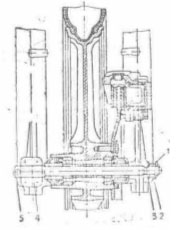
5. Maintenance5.1. EngineThe scheme of the engine with a gear box in a sectional view is given on an appendix 8. The outside surface of the engine should be always clean. The mud on the barrel and its head degrades cooling of the engine, and the availability on a casing of oil and gasoline can be the reason ignitions of a motorcycle. The application of the marks, not advised by a manual of gasoline and oil conducts to anticipatory wearing of parts of the engine and to fast carbon deposition in the barrel, head, on the cylinder piston and suppository, that invokes an overheating of the engine, degrades its launch. To a feed of the engine to apply gasoline and oils according to tab. 2.
5.1.1. Brief indicatings on removal of the engineRemoval of the engine to make in the following order:
To establish the engine in return sequence.
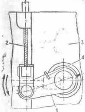
5.1.2. CouplingThe service of coupling is encompass byed to regulation of the gear cutoffs of coupling, which one consists of a cylinder with an eccentric and lever cutoffs of coupling, thruster with a cap, adjusting screws on the compression disk and clutch lever on a control surface, rope of coupling, restoring spring. Regulation of coupling to make in the following order:
Disassembly and assembly of a clutch to make without removal of the engine from the cradle in the following order:
Fig. 10. Regulation of coupling: 1 - lever cutoffs of coupling; 2 - rope of coupling; 3 - dextral cover; 4 - restoring spring
At knocking a circuit on idle speed or large sag (more than 15 mms) circuit to exchange. Assembly to make in return sequence, having paid attention on following:
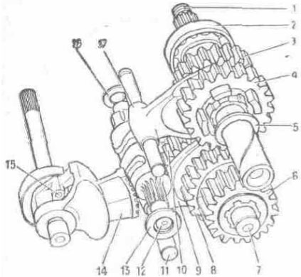
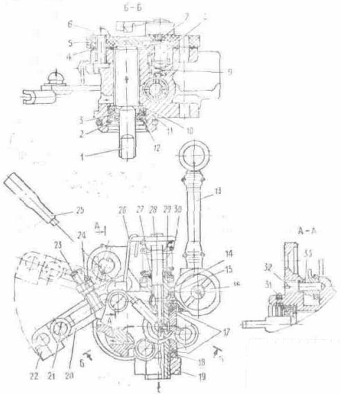
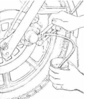
5.1.3. Gear boxThe service of a gear box consists in regular stock-taking of oil in a box and its well-timed replacement. The level of oil should be within the limits of a handhole. Replacement of oil to make on hot the engine, it is best at once after trip. To drain used oil through a foramen in bottom of a casing (fig. 11). To wrap up a fuse, to slosh 0,5 l of oil through a foramen under a cover of the hatch and to give to the engine to study 1... 2 min. After that oil to drain and to slosh 1 l of fresh oil (see tab. 2). Gear box four-stage (fig. 12) The disassembly and assembly of a gear box can be made without removal of the engine from the cradle. Disassembly:
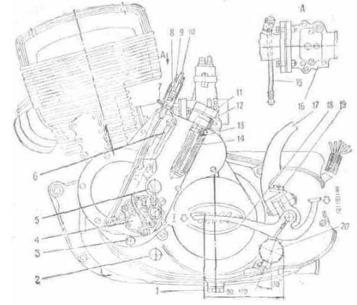
Fig. 11. The engine (left-side view): 1 - fuse of a drain of oil from a casing; 2 - handhole of a gear box; 3 - fuse of a drain of oil from capacitance of a lubricating system of the engine; 4 - oil pump; 5 - handhole of capacitance of a lubricating system of the engine; 6 - electrical wire of the valve - sensor; 7 - paper clip; 8 - screw adjusting; 9 - cap; 10 - rope of a metering device; 11 - fuse of a bulk foramen of capacitance of a lubricating system of the engine; 12 - ring strong; 13 - filter; 14 - body of the filter; 15 - oil line of an inlet pipe; 16 - carburettor; 17 - lever of a releaser; 18 - change-over lever of transmissions; 19 - fuse of a bulk foramen of a crankcase; 20 - step of the driver
For removal of the primary arbor and cylinders of forks of a gear-shifting to disassemble coupling to remove barrels. To turn unscrew screws, to remove a locking plate. To pay attention to arrangement of adjusting spacers on intermediate, primary arbors, arbor of a gear-shifting, that at assembly to put them on a place.
Fig. 12. A gear box: 1 - primary arbor; 2 - ball-bearing 204; 3 - cone II of transmission; 4 - cone II and IV of transmissions; 5 - persistent spacer; 6 - cone of a jackshaft; 7 - jackshaft; 8 - cone III of transmission; 9 - fork of switching I and III of transmissions; 10 - cone I and III of transmissions; 11 - cylinder of a shirt control fork; 12 - arbor of a gear-shifting; 13 - persistent spacer; 14 - quadrant of a gear-shifting; 15 - speed-control mechanism; 16 - adjusting spacers.17 - fork of switching II and IV of transmissions.
Assembly:
5.1.4. Disassembly and assembly of the engineFor disassembly of the engine to make operations described in sections "Coupling", "Gear box", "Generator", then:
After replacement or inspection of a crankshaft, glands assembly of the engine to make in return sequence. Thus it is necessary to pay attention on following:
For facilitation of dismantling and mounting of bearing boxs, glands and piston pin it is recommended halves of casing and cylinder piston to heat up to 70... 90 C. Assembly to make in return sequence:
To establish one lock ring of a piston pin in a flute of the cylinder piston piston pin, lubricated with engine oil, to paste into a foramen of a boss of the cylinder piston, mount the cylinder piston on the head of a connecting rod, holding an arm the cylinder piston, mild impacts of a wood hammer to push the pin of the cylinder piston into a foramen of the head of a connecting rod against the stop in the lock ring and to paste the second lock ring. To establish the gasket on a flange of a casing, to put on the gasket the wood fork or two bars, to establish on them the cylinder piston, to establish joints of piston rings against, locking pins, to shrink rings by a metallical belt, to lubricate a cylinder liner with motor oil and is cautious mount the barrel on the cylinder piston, is removed the fork from under the cylinder piston, to establish the barrel on a casing and to fix by nuts.
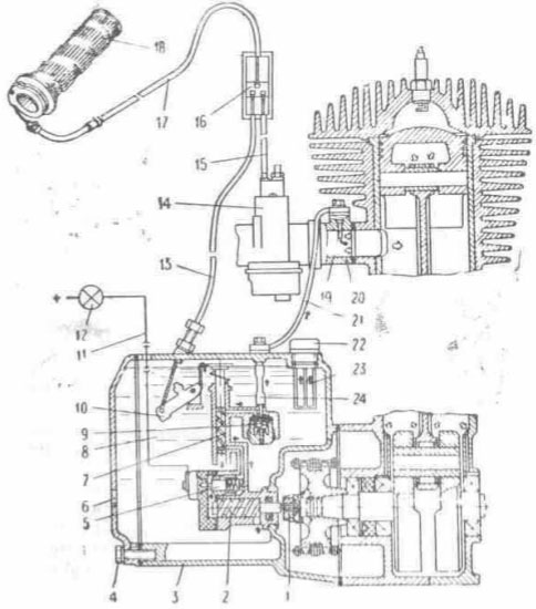
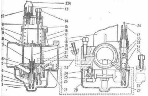
5.1.5. System of measured lubrication of the engineThe lubricating system of the engine provides lubrication of parts chancraft of the gear and barrel-cylinder piston of group of the engine and consists of oily capacitance 8 (fig. 13) in the left-hand cover of a casing 3, screw oil pump 2, presented in rotation from a crankshaft through a pipe connection 1 metering device 7, oil pump, arranged in a body, and metering device, controlled by a rope, 13, interlocked with a rope throttles of the carburettor 15, piston valve of the sensor 5 and diaphragm reverse valves 9, arranged in a body of an oil pump, oil lines 21 and 24, electrical wire 11 and caution light 12 "Oils" arranged in shield of devices. At chargings the gasoline recommends to check up availability of oil in oily capacitance on a handhole 6, arranged in a cover of oily capacitance. The volume of oil is lower than a level of a handhole (0,3 ltr) provides run 150... 200 kms. The indicated volume is stand-by. Before the beginning of exploitation of a motorcycle, in case of absence of oil in a transparent oil line, it is necessary:
At filling of an oil line on the earlier working engine is enabled to make accelerated filling of a transparent oil line at availability in the petrol tank of clean gasoline. Before the beginning of motion after long-lived parking of a motorcycle at the temperature of below minus 25 C (the cold engine) is necessary to warm up oil in oily capacitance by a running engine on a mode of idling speed during 2... 3 min. In case of usage of oils MC-14, MC-20 and MGD-14M it is necessary to dilute oil in oily capacitance by gasoline (5 % to a volume of oil).
Fig. 13. The scheme of a system of measured lubrication of the engine: 1 - coupling; 2 - oil pump; 3 - left-hand cover of a casing; 4- fuses of a drain of oil from capacitance; 5 - valve - sensor; 6 - handhole; 7 - metering device; 8 - oily capacitance; 9 - reverse valve; 10 - control lever; 11 - electrical wire; 12 - caution light; 13 - rope of a metering device; 14 - carburettor; 15 - rope of the throttle of the carburettor; 16 - distributive coupling; 17 - rope of gas; 18 - handle of the throttle of the carburettor; 19 - injector; 20 - inlet pipe; 21, 24 - oil line; 22 - fuse; 23 - filter
At temperatures below -15 C can descend delay of actuation (ignition) of a caution light OIL after a shutdown up to 10 min. The design of an oil pump does not demand its regulation in run up to 50000 kms. Diagnostic and regulation of an oil pump are possible only on special benches. It is forbidden to upset enamel cover of screws on a control lever of an oil pump and on a reverse valve. In case of impossibility to eliminate fault in a system of measured lubrication it is necessary to proceed to lubrication by a mix of oil with gasoline in proportions according to tab. 2, having disconnected the pompe from a crankshaft and having removed the coupling 1 (fig. 13). Regulation of free running of a rope of a metering device Regulation of free running to conduct in the following order:
Fig. 14. A lube pump: 1 - feeding screw; 2 - lock ring; 3 - sealing ring; 4 - gasket; 5 - cover; 6 - screw; 7 - terminal (saddle); 8 - cylinder piston; 9 - spring; 10 - spacer; 11 - casing of pump; 12 - spacer; 13 - oil line; 14 - sleeve of a metering device; 15 - gasket; 16 - reverse valve; 17 - O-ring; 18 - spacer; 19 - nut; 20 - control lever; 21 - screw; 22 - rod; 23 - adjusting screw; 24 - lock nut; 25 - electrical wire; 26 - thrust; 27 - O-ring; 28 - rod of a metering device; 29 - cap; 30 - spring; 31 - O-ring; 32 - axis; 33 - bush
5.1.6. Brief indicatings on replacement of parts of piston groupThe barrel on a minor diameter of the sleeve has four dimensional groups, according to which one produce cylinder pistons. New the barrel and cylinder piston select from identical groups till tab. 3. At replacement of the cylinder piston the installation it from following group (greater diameter) is enabled. The oval - barrel-type cylinder piston without rings should be displaced in the barrel under dead weight, split-skirt piston and rings - with an effort 3... 8 kgs. The table 3
The marking of group is indicated on a flange of the barrel and head of the cylinder piston. The cylinder piston and pin will be labeled by identical paint (green, white and black), which one is put on butt end of the pin and boss of the cylinder piston. At repair of piston group it is necessary to be guided by tab. 3, 4, 5. The table 4
The table 5
At the installation of repair pins of a foramen in bosses of the cylinder piston to finish up to the size ensuring a backlash 0... 0,005 mms, for the upper head of a connecting rod - 0,01... 0,03 mms. At replacement of piston rings it is necessary to establish rings in the barrel and to test interface gap of rings, he should be 0,25... 0,45 mms, if a backlash less than 0,25 mms, joints of rings grind.
5.2. The power supply system also issue
5.2.1. Petrol cranePetrol crane is joint with a sump and screen filters. The pen arm petrol crane has three positions (as directed on a body):
For clearing of a sump to bar petrol crane to turn away a sump and to flush parts in gasoline.
5.2.2. CarburettorThe scheme of the carburettor is rotined in a fig. 15. On-stream of motorcycle it is necessary to check up and to regulate engine run at minimum rotational speed of a crankshaft on a throwaway course, complianting of the engine to a control handle by the throttle. The frequency control of rotation geniculate has gorged idling has large value, as the system of idle acts as on small, and on a flooring motor loads. The fuel content given a system of idle, on a mode of full discovering of the throttle makes 5-10 % about, and on a mode of partial discovering of the throttle - 10-15 % from total of fuel consumed by the engine. Rpm control of a crankshaft idling to make in the following order:
If the rotational speed of a crankshaft is great, this operation to repeat until the minimum, steady rotational speed of a crankshaft will be obtained. Regularity of selected regulation idling to check up by sharp discovering and closing of the throttle. If the engine at sharp discovering of the throttle off or badly gains rotational speed, the mix is necessary slightly by minor turning home of a screw 18. If it is necessary to impoverish the engine gas at sharp closing of the throttle, a mix open of a screw. At exploitation of a motorcycle in different road and meteorological conditions it is necessary to concentrate or to lean a mix by a repositioning of a dosing needle 19 in the throttle 9. At lowering of a needle the mix leans, at raising - is concentrated. Mixture leaning to make at exploitation of a motorcycle at the altitude from 2000 m and more above sea level, and also in separate cases in process of wearings of the sprayer 3: At temperature the minus 15 C a needle is lower to raise on one - two divisions. Regularity of selected regulation of the carburettor to check up on color of isolator and central welding rod ignition plug:
At negative temperatures after launch of the engine up to its full warm-up use a fuel corrector, which one at turn of the lever up to 50 % from a general course provides indispensable mixture enrichment. At further turn of the lever the fuel corrector works as a launching device. The service of the carburettor consists in periodic clearing both washdown of its parts and channels from mud and gum residues. To flush parts and channels by clean gasoline, and if there is copious tarry deposits - solvent for nitropaints. The washed out parts and channels to blow out by a spray of compressed air. To not clean metering jets and foramens of the carburettor by a strand and other metallical subjects. At exploitation of a motorcycle to keep track of by a condition of the carburettor. Having found out even minor drip of fuel to tighten fasteners. The constant drip of fuel through a drain hole 27 testifies to a leakage of a stop needle of a fuel injection valve 24, float 25 or heightened level of fuel in the float chamber. For elimination of drip of fuel to flush the float chamber, delivering fuel a channel to test a condition of an elastic spacer on the valve, air-tightness of a float 25, to adjust a level of fuel, turning in a bracket of attachment of a stop needle 28. The level of fuel in the float chamber determines (at a removed cover) position of a plane of a symmetry of a float apart 13+-1,5 mms from a plane of the installation of a cover of the float chamber. Thus the carburettor to arrange by a float hill up. The regulation of free running of a rope of the throttle 13 carburettors (fig. 15) is made guide of a rope 12 in the following order:
Fig. 15. The scheme of the carburettor: 1 - metering jet of a fuel main system; 2 - cover of the float chamber; 3 - sprayer of a main system; 4 - metering jet of fuel idle; 5 - air passage of a main system; 6 - mixing chamber; 7 - body of the sprayer of a main system; 8 - carburettor body; 9 - throttle; 10 - spring of the throttle; 11 - emphasis - terminator of rise of the throttle; 12 - guide of a rope; 13 - rope of the throttle; 14 - adjusting screw of rise of the throttle; 15 - cover of the carburettor; 16 - balance channel of the float chamber; 17 - lock of a needle; 18 - screw of adjusting idle; 19 - dosing a needle; 20 - delivering fuel the union; 21 - foramen transient systems of idle; 22 - emulsion channel of a system of idle; 23 - air passage of a system of idle; 24 - stop needle of a fuel injection valve; 25 - float; 26 - emulsion channel of a launching device; 27 - drain hole; 28 - mounting bracket of a stop needle; 29 - fuel metering jet of a corrector; 30 - button of a float; 31 - needle dosing launching devices; 32 - plunger of a launching device; 33 - spring of a plunger; 34 - control cable by a corrector: 35 - jacket protective
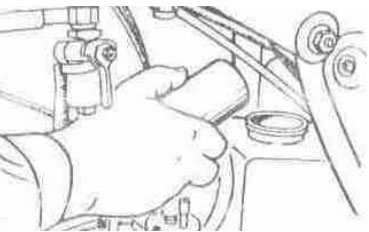
5.2.3. InhalerDepending on a dust content of roads, on which one the motorcycle is exploited, in batches to change oil (see tab. 2) and to flush a filter pack by gasoline. Oil to fill up in the collected air cleaner through mouth, having removed air scooping (fig. 16). In order to prevent a skew at assembly of an air cleaner a tightening of screws to make uniformly.
Fig. 16. A filling up of oil in an air cleaner
5.2.4. SilencerOn a motorcycle the dismountable silencer of exhaust gases is established. For removal of a silencer to turn away nuts of attachment of a flange of a receiver pipe to a fitting pipe of the barrel to turn unscrew a nut of attachment of a body to the cradle. For deleting a burn from an acoustic tube 2 (fig. 17) and cover to turn unscrew screws 3 attachments of a cover to remove a cover, to take out an acoustic tube and to furbish parts. At the installation of a silencer previously to fix a silencer to the cradle to establish a receiver pipe and to postpone the stall all nuts.
Fig. 17. A silencer: 1 - body; 2 - acoustic tube; 3 screws.
5.3. Undercarriage
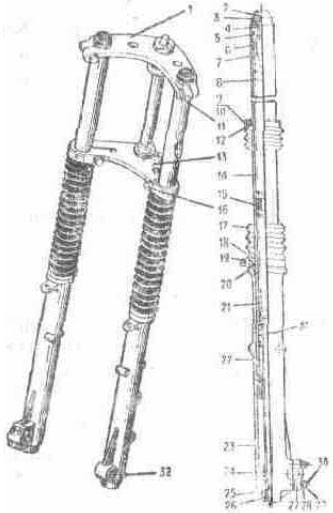
5.3.1. Suspension of a forward sprocket with the disk brakeOn a motorcycle the suspension of a telescopic type with a spring-hydraulic shock-absorber and air control is established. The shock-absorber is filled with oil in quantity according to tab. 2. Quantity of oil in a shock-absorber essentially influences performance curves of a shock-absorber. At an exuberant volume of oil pressure in a cavity of the rack sharply increases, that can result in mortality of a gland. The design of a shock-absorber envisions air control of rigidity depending on road conditions and load. The rollin of air in a shock-absorber is made by the pompe affixed to a motorcycle. For this purpose to establish a motorcycle on a central support, having supplied the hung out condition of a forward sprocket to increase displacement volume of a shock-absorber, to remove a rubber cover and cap in a top of a shock-absorber and through the valve of a reversing valve to make rollin. A recommended maximal pressure in a shock-absorber 0,04 MPa (0,4 kgs/sm2) to keep track of by , that the difference of pressure in shock-absorbers did not exceed 0,01 MPa (0,1 kgs/sm2).
Fig. 18. The suspension of a forward sprocket with the disk brake: 1 - bridge upper; 2 - valve of a reversing valve; 3 - cover; 4 - ring strong; 5 - ring strong; 6 - nut; 7 - cup upper; 8 - spring; 9 - screw; 10 - nut; 11 - bolt; 12 - clamp upper; 13 - bridge lower; 14 - barrel the worker; 15 - bush; 16 - bolt; 17 - jacket; 18 - ring lock; 19 - clamp lower; 20 - sealing ring; 21 - spring; 22 - cylinder piston with a piston ring; 23 - barrel of the tank; 24 - tip; 25 - spacer strong; 26 - screw; 27 - holder of an axis; 28 - spacer; 29 - nut; 30 - bolt; 31 - spring of an all-clear signal; 32 - screw
The maintenance behind shock-absorbers is reduced to the control behind availability of oil in racks and sustaining objection of air pressure. Before disassembly of shock-absorbers to eliminate air from the upper cavity of a shock-absorber by clicking the valve of a reversing valve; to remove a sprocket and shield (see section "Removal of a forward sprocket"), to ease through bolts in the lower and upper bridges and clamps of attachment of rubber jackets 17 to a lower bridge through the wood gasket by mild impacts of a hammer on a nut 6 to beat out the barrel 14 of bridges, to turn out a nut 6 of the barrel, to drain oil. To flush a shock-absorber by clean gasoline. To slosh oil. Further disassembly of a shock-absorber to conduct in the following order: To remove rubber jackets, having eased clamps of attachment them to barrels of the tank, and to take out both springs 8. To paste a steel band by the sizes 450X17X2,5 mm into a spline at butt end of the cylinder piston 22 or bar of length 450 mms a dia of 18 mms with a tumulus 10-150 and length 10 mms on the end in a foramen of the cylinder piston and, retaining it, to turn out a screw 26. To take out the barrel 14 of the barrel of the tank 23, to flush parts. A screw 26 to establish with application of a potting compound "Anaterm" or other oilproof potting compound, retaining the cylinder piston from turn. Assembly to run in of return sequence to slosh oil. At replacement of oil without disassembly of shock-absorbers, oil to drain through a foramen in bottoms closed by a screw 32.
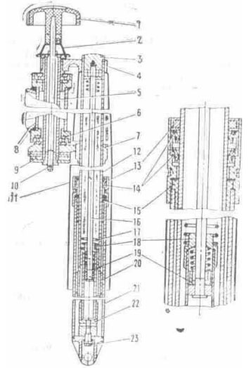
5.3.2. Suspension of a forward sprocket with the two-jaw brakeTo disassemble the telescopic fork in the following order: to remove a sprocket and shield, half lengths of a thread to turn unscrew a fuse 3 and body of a gland .13, to ease through bolts in the lower and upper bridges. Through the wood gasket by mild impacts of a hammer on a fuse 3 to beat out carrier a handset 12 of a upper bridge 4 to turn out a fuse 3 of carrier of a tube 12 and from a rod 16, to take out pen of the fork, to drain oil, to turn out a bolt 23, to get a shock-absorber together with a spring, to turn unscrew a body 13 glands and to remove a sliding tube 21. To flush parts.
Fig. 19. The suspension of a forward sprocket with the two-jaw brake: 1 - handle of the damper; 2 - spring; 3 - fuse: 4 - bridge upper; 5 - cylinder of a control pillar; 6 - ball-bearing; 7 - bridge lower; 8 - cradle of a motorcycle; 9 - disk of the damper; 10 - cotter pin; 11 - casing; 12 - tube of carrier; 13 - body of a gland; 14 - gland; 15 - bush of a sliding tube; 16 - rod; 17 - spring; 18 - tip of a hydraulic shock absorber; 19 - valve of a rod; 20 - cylinder piston of carrier of a tube; 21 - tube sliding; 22 - rack of a hydraulic shock absorber; 23 - bolt
Assembly to make in return sequence, having paid attention, that the pin on the rack 22 was mated with a fixing foramen in a tip of a sliding tube of the fork after that to wrap up a bolt 23 before failure. At assembly in each pen of the fork through a threaded foramen under a fuse 3 to slosh 0,175 l of oil (see tab. 2). In the rack of a shock-absorber there is a spring of an all-clear signal, which one in combination to a hydraulic system enriches the characteristic of the suspension.
5.3.3. Control pillarFor elimination of an axial clearance of a control pillar to ease through bolts in a upper bridge to remove the handle of the damper, to bend off a lock washer, to ease a nut of a upper bridge, to wrap up an adjusting nut against the stop, then to ease it on 1/8... 1/6 revolutions to wrap up a nut of a upper bridge and to turn in a lock washer. The lubrication (see tab. 2) is applied to bearing boxs of a control pillar.
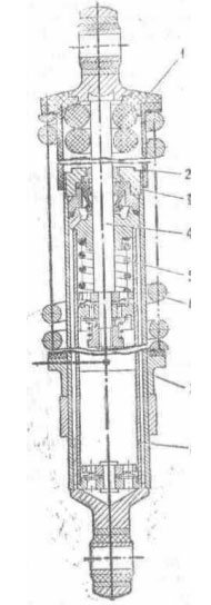
5.3.4. Suspension of a back sprocketThe suspension of a back sprocket consists of the pendulous fork and two hydraulic shock absorber. The axis of the pendulous fork is established in bearing boxs of rolling. The service of the pendulous fork is encompass byed to stock-taking of lubrication in bearing boxs and iterating it if necessary. Lubrication till tab. 2. Shock-absorber of the suspension of a back sprocket (the fig. 20) has regulation of contraction of a spring on three positions depending on load on a back sprocket. At increase of load to turn by a key the regulator clockwise. For replacement of oil to remove a shock-absorber to squeeze a spring 6 suspensions up to an output of reference semirings 1, to remove a spring 6, sleeve 2, to turn unscrew a body of a gland 3, to take out a rod 4 and barrel 8 and to drain oil. To flush parts. Assembly to make in return sequence. At assembly to slosh 0,075 l of oil (see tab. 2). The shock-absorber has a spring of an all-clear signal, which one in combination to a hydraulic system enriches the characteristic of the suspension.
Fig. 20. A shock-absorber of the suspension of a back sprocket: 1 - reference semi ring; 2 - sleeve; 3 - body of a gland; 4 - rod; 5 - spring of an all-clear signal; 6 - spring; 7 - regulator; 8 - barrel
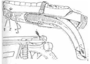
5.3.5. Saddle with shieldFor removal of a saddle to click the thruster 1 (fig. 21) detent 2 to uplift a forefront of a saddle and, submitting a saddle forward, to remove it from the cradle, to disconnect wires.
Fig. 21. Removal of a saddle: 1 - thruster; 2 - detent
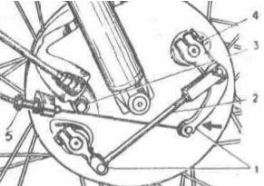
5.3.6. SprocketDepending on a complete set on a motorcycle the forward and back sprockets unit-cast with trunks of the miscellaneous size and sprocket with spokes with trunks of one size, both interchangeable, and not interchangeable can be established. Removal of a forward sprocket. For removal of a forward sprocket with the disk brake (fig. 22) to ease nuts of attachment of an axis in the dextral rack of a shock-absorber, open and to turn unscrew a nut (thread left-hand) attachment of a wheel axle; to turn out screws of attachment of a casing of the disk brake; to raise hill up on a flexible roller a casing; to turn unscrew a bolt of attachment of a flexible roller, to take out a flexible roller from the drive, to remove a casing from a flexible roller, to take out an axis 5, to remove a sprocket from shock-absorbers of the suspension and grip of the brake by motion downwards and forward. ATTENTION. After removal of a sprocket to not depress the lever of a hand brake, as there can be an outflow of brake fluid and contact of brake shoes, it is required pomp of a brake assembly.
Fig. 22. Removal of a forward sprocket with the disk brake: 1 - cotter pin; 2 - nut; 3 - spacer; 4 - holder of an axis; 5 - axis
In a sprocket the bearing boxs with one protective spacer (semiclosed) are established. For lubrication of the bearing box to take out the bush with extrude by a flange and gland, if necessary the bearing box to flush it and to lubricate (see tab. 2). The installation of a sprocket to conduct and return sequence. Removal of a back sprocket. For removal of a back sprocket to remove a saddle to turn unscrew a nut 2 (fig. 29) attachment of an axis (thread left-hand), to take out an axis and strut sleeve, to remove a sprocket from splines of a hub and from brake shoes, submitting it to the left, forward and hill up. At assembly a strut sleeve to establish to a small dia to a hub of a sprocket. For lubrication of bearing boxs to turn unscrew a body seal to remove a decorative cover, extrude the left-hand bearing box through a foramen of the dextral bearing box, to take out a strut sleeve and lock ring, the dextral bearing box, to flush and to lubricate parts. It is necessary to fill in with lubrication a cavity between the bearing box and fixing spacer. The bearing box by a protective spacer out. The installation of a sprocket to make in return sequence. Removal of a forward sprocket with the two-jaw brake it is drumtype. For removal of a forward sprocket to disconnect a rope of the drive of the brake of a forward sprocket from the lever of the brake on a control surface, previously having squeezed the lever 1 (fig. 23) in the party indicated by a finger to turn unscrew a bolt 3 and to take out a flexible roller, to ease a through bolt of attachment of an axis in a tip of the left-hand sliding tube, to turn out an axis (thread left-hand) and to remove a sprocket from pens of the fork. For lubrication of bearing boxs to turn unscrew a body seal to remove a decorative cover, the left-hand bearing box through a foramen of the dextral bearing box, to take out a strut sleeve and lock ring, extrude the dextral bearing box, to flush and to lubricate parts (necessarily to fill in with lubrication a cavity between the bearing box and fixing spacer). The bearing box extrude by a protective spacer out.
Fig. 23. Removal of a forward sprocket with the two-jaw brake: 1 - levers; 2 - thrust; 3 - bolt; 4 - check box; 5 - screw adjusting
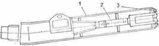
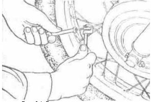
The installation of a sprocket to conduct in return sequence. Pulling of spokes of a sprocket.
Fig. 24. Tension control of spokes
At exploitation of a motorcycle with sprocket with spokes by sprockets to keep track of by a tension of spokes, in a case is loosed uniformly to tighten them on all circumference of a hoop For an avoidance of a spoke at it bowse in to restrict a spoke by adaptation (fig. 24) for squeeze out of an axis of a chain link, under a screw which one to establish a special bearing from a complete set of the tool. Minor bowse in of spokes to make without removal of the trunk from a hoop. In case of replacement or considerable braces of spokes, in order to prevent a puncture of the chamber to remove the trunk and sleep to pour the end, outstanding from the nipple, of a spoke.
5.3.7. BrakeThe brake assembly of a motorcycle consists of gears established on each sprocket, and two independent drives of control by them. On a forward sprocket of a motorcycle the disk hydraulically operated brake or two-jaw brake can be established drumtype. The toe mechanical drive serves for inhibition of a back sprocket of a motorcycle. Service of the disk brake of a forward sprocket. The hand brake of a forward sprocket hydraulically-driven regulations does not demand. The inspection of brake shoes is made without removal of a sprocket, through an oval window of a grip with a rubber cover. The chocks are subject to replacement at wearing of friction plates up to depth of 1 mm. For replacement of braking chocks to turn unscrew a lock nut of a bolt of attachment of a body of a grip of the brake to turn out a bolt from guide of chocks, to turn counter-clockwise on the routing pin a body of a grip of the brake, freeing it access to brake shoes. To remove worn chocks from guide of chocks and to establish new. To pay attention to a regularity of fastening of chocks by two latches spring. On a mobile brake shoe to fix no-screech a lamina, the direction of a finger on a lamina should coincide a sense of rotation of a sprocket.
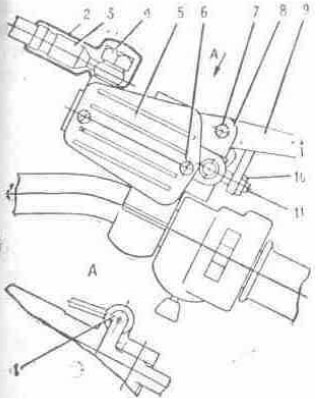
Fig. 25. The drive of a hydraulic brake: 1 - switch "stop"; 2 - jacket; 3 - hose pipe; 4 - bolt; 5 - cover; 6 - screw; 7 - axis; 8 - body; 9 - lever; 10 - lock nut; 11 - screw adjusting
Assembly of the brake to conduct in the following order: to shift the cylinder piston inside of bodies of a grip, to turn a body in initial position on the routing pin, to fix a body from guide of chocks by a bolt with a lock nut. In case of removal of a brake disk, it is necessary to make a label on the disk and hub of a sprocket. The installation to make on labels. Replacement of brake fluid in a hydraulic drive of the brake of a forward sprocket. The brake fluid (tab. 2) is applied to charging a hydraulic drive of a forward sprocket. For replacement of a liquid:
Fig. 26. Replacement of brake fluid: 1 - valve of air discharge
In case of hit of air in a hydraulic-circuit system and for the control of a brake assembly after replacement of brake fluid, it is necessary to conduct deaerating. For this purpose:
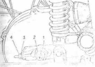
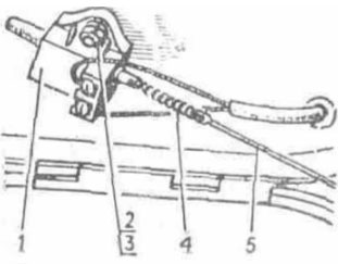
Regulation of the brake of a back sprocket. To establish the lever of the brake of a back sprocket 3 (fig. 9) hook, that in an extreme upper position he rested on a cylinder 4 steps of the driver, and with an adjusting screw (fig. 27), arranged in a casing of a sprocket to supply free running of a pedal of the lever of the brake downwards on 5... 15 mms.
Fig. 27. Regulation of the brake of a back sprocket
Regulation of the two-jaw brake it is drumtype. Regulation to make in the following order:
For improvement of activity of the drive of the brake of a forward sprocket in the vernal-autumnal season we recommend a cable rope of a rope of the forward brake to oil motor automobile or brake fluid, and adjusting screws to dispose a groove downwards. The lubrication is made by dipping of a cable rope in capacitance with oil and subsequent movings of a shell (5-10 times) on a cable rope.
5.3.8. Circuit of the drive of a back sprocket
Fig. 28. The installation of the latch of the lock of a circuit, control of a tension of a circuit
For deposition of lubrication on a circuit to separate the lock to remove a circuit, to flush and to plot lubrication (see tab. 2) or to remove a dextral cover of a casing and, turning a back sprocket to plot on a circuit lubrication. At assembly circuit links to connect by the lock, latch to establish by a cut in the party inverse to motion of a circuit (a fig. 28). Tension of a circuit to check up by clicking the lower rubber jacket of a circuit hill up and downwards on middle of a jacket (fig. 28). At moving of a circuit more than 30 mms to tighten it, changing a position of an axis of a back sprocket by a nut 3 (fig. 29). Having adjusted a circuit to wrap up nuts of an axel, axis and tie rods. In case of a large extract of a circuit to truncate it on two links, using a coupling link and tool from a complete set. At regulation of a circuit to monitor, that the sprockets were in one plane. Regulation of the installation of sprockets in one plane to make on risks on the pendulous fork and ledges of tie rods of a circuit. After tension control of a circuit it is necessary to make regulation of the brake of a back sprocket.
Fig. 29. Tension control of a circuit: 1, 2, 3 - nut; 4 - lock nut
5.3.9. Reduction gearbox of a speedometerThe service of the reduction gearbox of a speedometer is encompass byed to lubrication of pinions. For this purpose to remove a casing of the disk brake to turn unscrew a bolt, to take out a flexible roller, bush a cone. To flush and to lubricate parts. Assembly to make in return sequence.
5.4. Electric equipmentThe scheme electrical is given on appendix 7. The electric equipment of a motorcycle actuates: sources of electrical power - battery accumulative and generator;
5.4.1. GeneratorThe generator (fig. 30) alternating-current single-phase with excitation from permanent magnets. The rotary table of the generator is established on a tumulus of a dextral axel of a crankshaft of the engine, a stator - in a cover of the generator or it is ground, fixed in a crankcase. The stator has two separate winding: charging and power. The charging winding is connected directly to the switchboard and serves for a feed of an ignition system of the engine, the power winding through rectifier-regulator provides a feed of devices of illumination, signalling system and battery charging accumulative.
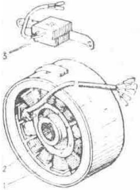
Fig. 30. The generator and sensor of ignition: 1 - rotary table; 2 - stator; 3 - sensor of ignition A feed of a system of ignition implements an alternating current, remaining customer - through rectifier-regulator of voltage by a direct current. The generator has no sliding contacts and friction of parts, its service is reduced to overseeing by a condition of an electrical insulation, connections of wires both security of attachment of a rotary table and stator. The serviceability of a generating set (generator - rectifier-voltage regulator) is checked up with the help of the voltmeter of a direct current with a scale graduation value 0,1 V. The voltmeter is hooked up to the terminal "+" rectifier-voltage regulator and "-". On mean engine speed at hooked up battery accumulative and live distant light of a head lamp the voltage should be 13,7... 14,7 V. The deviation of voltage from indicated values testifies to fault of a rectifier - voltage regulator or generator. Removal of the generator from the engine to make in the following order:
If the stator is established ground, fixed in a casing, to turn unscrew four screws of attachment of a stator to the basis, to remove a stator with a bundle. The installation of the generator to make in return sequence.
5.4.2. Accumulator batteryThe accumulator battery is the power source at an inoperative engine. The terminal "-" battery incorporates with "-" of a motorcycle. The return hooking up of terminals is invalid, as results in mortality of electronic devices, other clusters of electric equipment and battery. Actuating, exploitation and service of the battery are described in the affixed maintenance instruction of the battery accumulative. In bridge accumulative the condenser by capacitance 2200 mF, intended for smoothing of oscillations of rectified voltage and maintenance of normal activity of customers of the electric power of a motorcycle is connected at mortality of an accumulator battery or its absence.
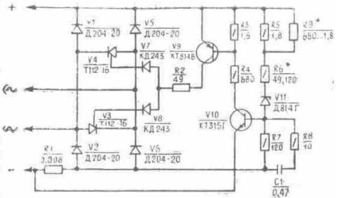
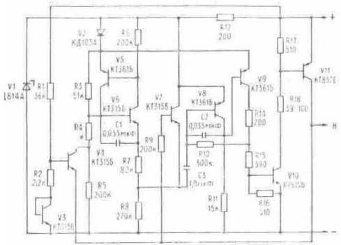
5.4.3. Rectifier-voltage regulatorThe rectifier-voltage regulator (fig. 31) or voltage regulator is intended for a rectification alternating-current of generator, maintenance of voltage of the generator, in predetermined thresholds and maintenance of a reliable operation of all system of electric equipment, hooking up which one in a system variously (see scheme electrical in the appendix 7).
Fig. 31. The scheme of a rectifier-voltage regulator BPV 21-15 In order to prevent violation of thermal operational mode of the rectifier - regulator in batches (not less often than once per six months) it is necessary to clean by its sweeper of dust and other contaminations. Is not enabled to dust by metallically subjects and to upset a factory seal in the season of guarantee run of a motorcycle.
5.4.4. Installation of ignitionThe initial lead angle of ignition is determined by a positional relationship of the sensor of ignition and rotary table of the generator, on-stream to regulation is not subject. At engine run the ignition system automatically changes a lead angle of ignition depending on crankshaft speeds.
5.4.5. Switchboard electronicThe switchboard electronic, is intended for accumulation of energy giving by the generator, and transmission it on an induction coil. The switchboard is executed in a plastic hermetically closed body, that eliminates hit of a moisture. Maintenance does not demand, to repair is not subject.
5.4.6. Sensor of ignitionThe sensor of ignition (fig. 30) is intended for creation of a control pulse for the switchboard of ignition. On-stream maintenance does not demand also to repair is not subject.
5.4.7. Induction coilThe induction coil (fig. 32) is intended for transformation of energy, stored in the switchboard, in a high-voltage impulse given on an ignition plug. On-stream it is necessary to clean a coil of dust and other contaminations. To repair is not subject.
Fig. 32. An induction coil
5.4.8. Ignition plugThrough 2500-3500 kms to check up a condition of a suppository, at a fouling and oiling to flush I shine in clean gasoline and to dry. Backlash between welding rods of a suppository to test by a probe. At regulation of a backlash is cautious to turn in a lateral welding rod. I shine in a jack to establish with the O-ring.
5.4.9. Tip Ignition plugTip Ignition plug (the fig. 33) connects an ignition plug to a high-voltage wire of a coil of ignition and provides a decrease of radio interference to the permissible norms. It is on-stream recommended in batches to check for security of attachment of wires in a tip and in an induction coil, to purge a tip with the purpose of dusting off between a screen and body, to wipe a tip inside. The wire should be screwed in a tip against the stop.
Fig. 33. A tip Ignition plug: 1 - body; 2 - resistor; 3 - wire; 4 - screen
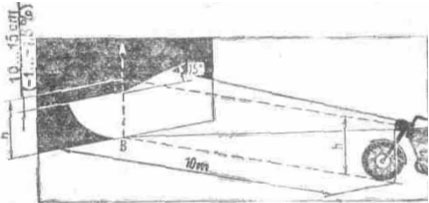
5.4.10. Head lampThe head lamp has two lamps: main light with two threads (short-range and distant light) and lay light. For best usage of light qualities and reduction of blinding operating the head lamp is necessary for adjusting. Before regulation a motorcycle to establish on to a horizontal site perpendicularly to a Screen apart 10 m. Load on a motorcycle at regulation - driver. Regulation to make at live short-range light pursuant to sectoring a screen (fig. 34), thus the longitudinal vertical plane of symmetry of a motorcycle should be intercepted with a screen through link AB.
Fig. 34. Regulation of a head lamp
5.4.11. Disconnecting switches of XOFF of brakesThe disconnecting switches of XOFF of brakes of forward and back sprockets serve for actuation of a light signal at inhibition of a motorcycle. Regulation of a time of engagement of a signal in random change of a position of the lever of the brake of a back sprocket to make by a runway of the disconnecting switch 1 (fig. 35) at its loosened attachment. The lamp of XOFF should ignite prior to the beginning inhibition of a sprocket. The disconnecting switch of XOFF of the brake of a forward sprocket is established in a bracket of the lever of the brake of a forward sprocket and regulation does not demand.
Fig. 35. Regulation of the disconnecting switch of autopodiums: 1 - disconnecting switch of XOFF; 2 - screw; 3 - nut; 4 - spring; 5 - thrust
5.4.12. Sound signalThe sound signal of maintenance does not demand. The regulation of force of sounding can be made by an adjusting screw arranged on a body. 5.4.13. Fuse The fuse consists of bodies 1 (fig. 36), cover 3 and fuse 2 on 10 A. The safety device is adjoined to the terminal "+" rectifier-regulator of voltage. At combustion of a fuse to eliminate the cause called combustion, and to exchange it, having separated a body with a cover. To keep track of by a condition contact connection of the safety device, cleaning them from contamination.
Fig. 36. The fuse: 1 - body; 2 - fuse; 3 - cover
5.4.14. Interrupter of the indexes of turnsThe interrupter of the indexes of turns IZHRP-4 (fig. 37) is intended for discontinuing the power supply circuit of caution lights of the indexes of turns and control of serviceability of these lamps. The interrupter of the indexes of turns having arranged on the cradle under the petrol tank. He has protection against short circuits in a circuit of caution lights and maintenance does not demand. To repair is not subject.
Fig. 37. The electrical principal diagram of the interrupter of the indexes of turns IZHRP 4: "+" - positive conclusion; "-" - negative conclusion ("weight"); H - conclusion of load
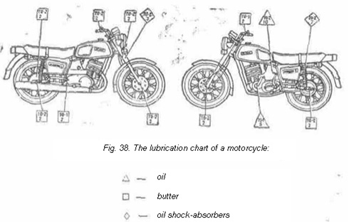
5.5. Kinds and periodicity of maintenanceThe maintenance actuates washing, refuelling, lubricating, monitoring, fastening, adjusting and other kinds of activities. On periodicity and the labour inputs of works on hand are subdivided into daily services (DS), first technical service (TS-1), second technical service (TS-2). Daily services to make before each departure. The periodicity TS-1 and TS-2 is established on transverse depending on the operation conditions (see tab. 6, 7), but not less often two yearly for TS-1 and one time annually for TS-2. The lubrication chart of a motorcycle is rotined in a fig. 38. The table 6
5.5.1. Order of maintenanceThe table 7
5.6. Possible troubles of a motorcycleThe table 8
The table 9 Technique of detection of the causes of faults of an ignition system
|
|||||||||||||||||||||||||||||||||||||||||||||||||||||||||||||||||||||||||||||||||||||||||||||||||||||||||||||||||||||||||||||||||||||||||||||||||||||||||||||||||||||||||||||||||||||||||||||||||||||||||||||||||||||||||||||||||||||||||||||||||||||||||||||||||||||||||||||||||||||||||||||||||||||||||||||||||||||||||||||||||||||||||||||||||||||||||||||||||||||||||||||||||||||